FLUID COMPONENTS INTERNATIONAL LLC FLT93 Flow Switch Series
This page is subject to proprietary rights statement on last page
2 Doc. No. 06EN003312 Rev. D
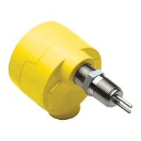
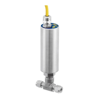
Install the flow element, with the flow arrow (shown on Page 1) in the direction of media flow. The element should be in the
center line of the process pipe or rectangular duct. The flow arrow flat area is to be parallel ±2° with the media flow. If the
remote control circuit option is used, the serial number of the flow element must match the serial number of the electronic
enclosure. Below are the most common instrument mounting options.
Flow Element Installation
Wiring Preparation
Before the instrument is opened to install the wiring, FCI recommends that the following ESD precautions be observed:
Use a wrist band or heel strap with a 1 megohm resistor connected to ground. If the instrument is in a shop setting there should
be static conductive mats on the work table and floor with a 1 megohm resistor connected to ground. Connect the instrument to
ground. Apply antistatic agents such as Static Free made by Chemtronics (or equivalent) to hand tools to be used on the
instrument. Keep high static producing items away from the instrument such as non-ESD approved plastic, tape and packing
foam.
The above precautions are minimum requirements to be used. The complete use of ESD precautions can be found in
the U.S. Department of Defense Handbook 263.
Unscrew the instrument’s lid. Remove the control circuit by prying up on the metal transformer tabs (under the serial
number label) while rocking the transformer back and forth. This exposes the wiring block shown on the next page.
Flanged Integral Instrument Shown in a Customer Process
NPT Integral Instrument Shown in a Customer Process
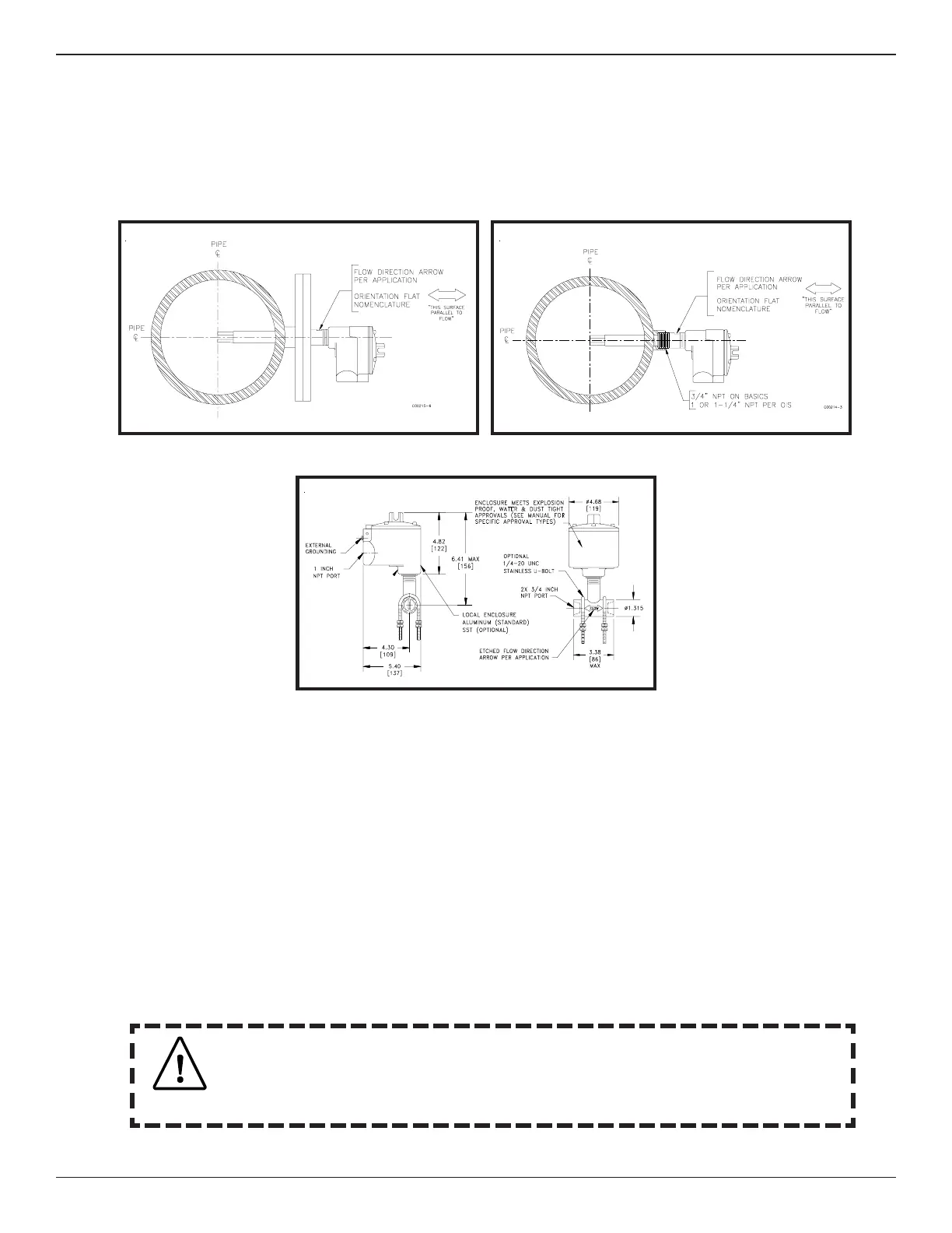
FLT93L Local Inline Mount
Be sure the instrument is configured correctly for the applied input power. If Factory Mutual
specifications were ordered, the input power should be 115 VAC and the instrument jumpers should be set
for 115 VAC as shown on Page 4. Otherwise, the power input has been set for 220 VAC unless otherwise
specified.
Caution
 Loading...