10 ©Firey AB (Oktober 2016)
This option provides the user with a method of programming the
unit number into the non- volatile memory of the microprocessor.To
program the detector address number, rst remove power from the
detector. Then toggle the program option “ON” and set the rst ve
switches on the user selectable interface (USI) to the detector address
number.
In program mode, the USI becomes a binary programmer as illustrated
in Table 6. When a switch is toggled “ON”, it will equal the binary
weighted number. These binary weighted numbers are added
together when a multiple number of switches are switched “ON” (i.e.,
if SW2 and SW3 were closed, then the detector number would equal
a 6).
Table 6 Binary Weight for Switch States “ON”
SW1 SW2 SW3 SW4 SW5
1 2 4 8 16
When power is applied to the detector. The detector will sense that
it is in program mode and read the rst ve switch positions. From
the switch setting, it will determine the detector number. Once the
number has been determined, the detector will enter it into the non-
volatile memory of the microprocessor. Next, the amber LED will ash
“ON” a certain number of times. The number of ashes will be equal
to the detector’s address number. Then it will hold the fault relay and
amber LED “ON” constantly for about 10 seconds. Then the detector
will repeat ashing the detector address number and the delay time. It
will continue this mode for up to 5 minutes.
Once you are sure that the proper number is programmed, then shut
the power “OFF” and set the USI options to suit your application.
Reference the section on the USI if you are not sure which option is
best for your application or call a Firey AB application engineer.
Note: In the case that the program option switch is left “ON” and the
detector is installed on the network. The detector will go through the
same process as explained previously, but after 5 minutes the detector
will resume the last USI setting that it had prior to going into the
program mode.
Maintenance and troubleshooting
Model 660 and 860 ame detectors are designed for years of
trouble-free operation with minimal attention. Periodic cleaning of
the optical surfaces is essential, however, for maintaining reliable re
protection. The frequency of required cleaning will be determined
by the environmental conditions in and around the installation. The
detectors should be regularly inspected for a build-up of dust or other
contaminants on the optical surfaces.
The detection specications presented in this manual are predicated
on performance with clean sensor windows. Contaminants such as
dust, oil and paint will reduce sensitivity. Severe contamination on the
light guides or sensor windows will cause a failure of the auto-test.
A detector that fails auto-test due to dirty optical surfaces may be
capable of detecting re, but its eectiveness will be limited from 50 to
70% obscuration.
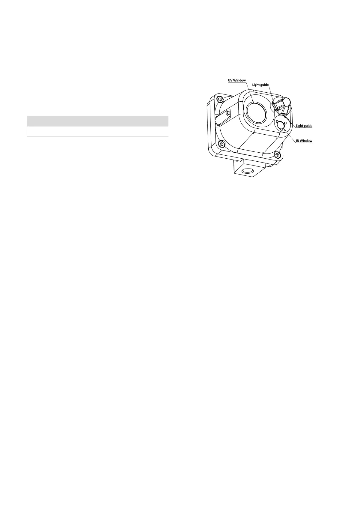
Cleaning Procedure:
Locate the following optical surfaces: (Figure 11)
Models 660-XX1XX
1. UV Sensor Window
2. UV Light Guide End
Model 860-XX1XX
1. UV Sensor Window
2. UV Light Guide End
3. IR Sensor Window
4. IR Light Guide End
Note: Models 660-XX0XX and 860-XX0XX are not equipped with light
guides. Clean the optical surfaces with a cotton swab wetted with
commercial liquid glass cleaner, ammonia, methanol, or isopropyl
alcohol. Rinse with clean water and dry with lens quality cloth. Repeat
with methanol if needed to remove smudges.
Caution: Wiping with excessive force or inappropriate materials may
scratch the optical surfaces and impair performance.
Figure 11 – Optical surfaces
Troubleshooting:
*WARNING* Do not attempt to repair a detector. Study these
troubleshooting guidelines and review the referenced sections of the
manual prior to performing maintenance on the re detection system.
New Installations:
Starting with Revision E Software, when the detectors are in
operational mode, and amber LED will be visible for one second
approximately every ten seconds. If any or all the detectors fail to
operate, check the system wiring and power supply. Tight, reliable
wiring connections are essential, as are low-resistance connections
from every detector housing to earth ground. Measure the voltage
between terminals 8 and 10 at the detector locations to verify that the
supply voltage is within range.
Note: Voltage at detectors installed farthest from power source will be
lower than the no-load supply voltage due to line losses. Maximum
load condition occurs during manual test.
The Model 660 and 860 ame detectors employ sensitive and
sophisticated electronic circuitry in the re detection process. Power
line transients or excessive power supply ripple may therefore cause
erratic or intermittent operation. DC-powered detectors function best
with ripple-free (less than 1 percent) supply voltage; power supply
ltering may be necessary to improve performance.
Note: For reliable operation, the instantaneous supply voltage at the
input to any detector must not fall below 20 Vdc or exceed 32 Vdc.
Failure To Alarm:
Upon detection of re, the re outputs will activate and the red LED,
visible through the UV sensor window, will turn “ON”.
If during testing, a detector fails to alarm, inspect the sensor windows
for cleanliness. Clean sensor windows are essential for eective
optical re detection. Clean all the optical surfaces per the cleaning
procedures previously described and retest the detector.
Should the detector continue to be inoperative, check the supply
voltage and all associated wiring. Incorrect power supply voltage or
loose connections will cause marginal or intermittent performance.
DMLieferant Тел.: +7 (499) 990-05-50; +7 (800) 775-29-59 dmliefer.ru
 Loading...