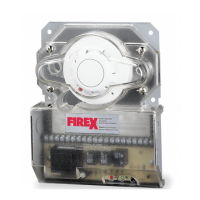
Electrical Installation
WIRING
Prior to connecting power to the Firex 2650-560 and 2650-561 duct units, determine the correct input voltage and ensure it is connected to the
correct terminals. (Refer to power connections)
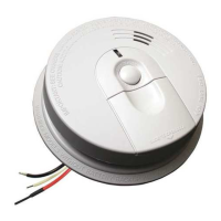
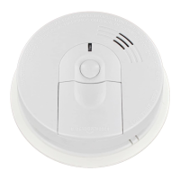
24V A.C./D.C.,Terminals 5, 6 ; 115V A.C., Terminals 1, 2, 3 ; 230V A.C., Terminals 1, 2, 4
POWER CONNECTIONS
:
CAUTION:
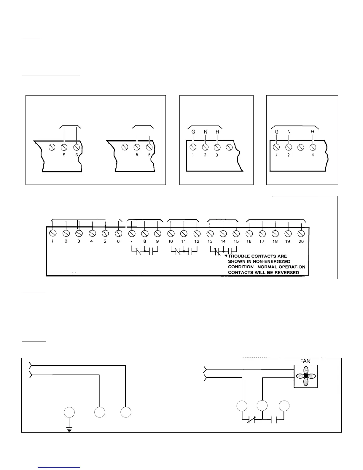
For terminals 7, 8, 9 - 10, 11, 12 do not use looped wire under terminals. Break wire run to provide supervision of connections. To test the
correct operation of the duct smoke unit, excluding the detector head (see functional testing page 4) remove detector head and connect one
of the appropriate dedicated power sources to the applicable terminals (See above). Replace detector head and the unit will be energized
(The green led will be illuminated). When pressing the test/reset button the red Alarm led will be illuminated. In the event of a fire alarm,
certain equipment may have to be shut down. A shut down will be achieved by interrupting the supply source to that particular piece of
equipment when wired as indicated below.
EXAMPLE
:
Fan Supply Source
7
9
NC C NO
RELAY
P P
1
Dedicated INPUT Voltage
FirexDuct Unit
In alarm, 7 and 8
will open,
interrupting supply
to fan
5
24V A.C./D.C. INPUTS
Terminals 5, 6
24 V.A.C.
50/60 HZ 0.2A MAX
8
Form No.MA 124 11/98 Rev A
24 V.D.C.
0.1A MAX
115 V.A.C. 50/60 Hz
0.1A MAX
115V A.C. INPUT
Terminals 1,2,3.
230 V.A.C. 50/60 Hz
0.1A MAX
230V A.C. INPUT
Terminals 1,2,4.
See
Power
Connections
ALARM
CONTACTS
12 A
ALARM
CONTACTS
12 A
*TROUBLE
CONTACTS
10-A
REMOTE
ACCESSORIES
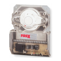
FIREX DUCT SMOKE DETECTOR
24 V.A.C. OPERATION 24 V.D.C. OPERATION 115 V.A.C. OPERATION 230 V.A.C. OPERATION
+
-
 Loading...