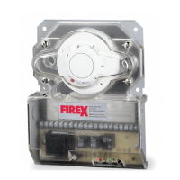
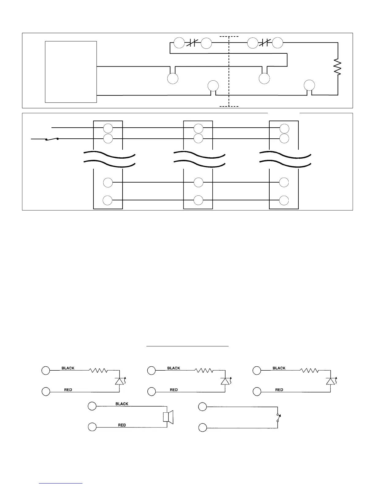
Fire Alarm Control Panel Wiring
Common functions include one or all of the following:
Remote Common Alarm indication, Remote Pilot indication, RemoteTtrouble indication, Remote Common Reset, Common Shutdown,
and Common Visual indication.
Common Fault indication ( when green pilot led is extinguished) can not be achieved on the Firex Duct Units. Individual Remote Pilot
led’s must be installed to monitor detector head or power source removal for each unit.
A Common Trouble (Yellow) led can be installed on any unit to monitor the removal of a detector head. When installing a Common
Trouble led which will be illuminated when any detector head is removed, a jumper wire on each unit must be installed between
terminals 13 and 20. Terminals 14 and 16 between each unit must be wired in series.
With multiple units wired in a common function fashion and an alarm or functional test is initiated, all duct unit alarm leds will be
illuminated. In a common alarm state only the led of the detector head in alarm will be illuminated, all other head leds will be off.
With multiple units connected, a common reset will be achieved by interrupting the supply voltage.
REMOTE
ACCESSORY WIRING
Remote accessory terminals 16 to 20 are not supervised and the output voltage will be present when the duct detector is in alarm or
the test/reset switch is operated.
For the 0543 & 0544 accessories with a Trouble L.E.D. (yellow), a jumper wire must be placed between Terminals 13 and 20. The Trouble L.E.D.
(yellow) will illuminate when the sensing head of the detector is removed.
UL
Listed
Fire
Alarm
Control
Unit
14
15
14
15
11
12
11
12
Firex Detector
#1
Firex Detector
#2
EOL
End
of
Line
Fig. 1
Strobe
&
Horn
Negative
Positive
Negative
Positive
6
Green
“Pilot”
Led
Form No. MA 2650 11/98 Rev. A.
19
20
Negative
Positive
Red
“Alarm”
Led
17
17
16
16
Negative
Positive
Yellow
“Trouble”
Led
14
16
Installation requiring common functions must be wired as shown in fig. 2.
Input Power Source
Will Be Either
24V, 115V or 230V
Fig. 2
DUCT UNIT #1
DUCT UNIT #2
DUCT UNIT #3
COMMON INPUT
POWER
COMMON RESET
INPUT
POWER
INPUT
POWER
17
16
Key or
Push button
“test/Reset”
Switch
18
18
20
20
P
P
P
P
P
P
18
20
 Loading...