In installations where it is impossible to adhere to the six duct width requirement, units can be installed closer but as far from inlets, bends or
deflector plates as possible. Should this situation arise, check velocity readings in the duct prior to the duct smoke unit installation. Ensure the
duct smoke unit pressure differential complies with the unit specifications. The pressure differential between the input sampling tube and
exhaust tube for the Firex series duct smoke unit should be greater than 0.01 inches of water and less than 1.2 inches of water.
3) Identify a location for the installation of the duct unit that will permit easy access for viewing and serviceability.
4) Install duct units in the return air side of an HVAC unit prior to the air being exhausted from the building or diluted with outside air.
5) When installing duct smoke units down stream of filters, fires occurring in the filters will be detected, but if the filters become blocked
insufficient air flow through the duct unit will prevent the correct operation of the duct detector.
6) Where possible, install duct detectors upstream of air humidifiers and downstream of dehumidifiers.
7) To prevent false alarms, the duct detector should not be mounted in areas of extreme high or low temperatures, in areas where high
humidity exists or in areas where the duct may contain gases or excess dust.
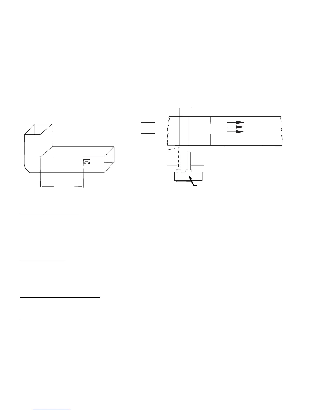
6 Duct Widths
Minimum
Bend or Other
Obstruction
Insert Red Stopper
This End of Inlet Tube
Air Flow
Tube Support Hole Only for Ducts
Greater than 3 Feet Wide
Duct Width
Air Flow
Direction
Set
Screw
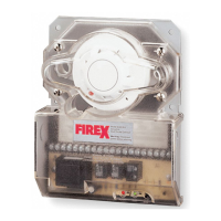
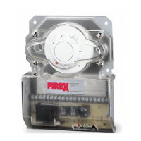
2650 Duct Smoke
Detector
SAMPLING TUBE ASSEMBL
Y
:
Sampling tubes are to be ordered separately in one of the 3 standard lengths.
552 For duct widths of 1.0’ TO 2.5’
553 For duct widths of 2.5’ TO 5.0’
554 For duct widths of 5.0’ TO 10.0’
The standard sampling tubes are steel tubes with air intake holes drilled down the entire length of the tube. These tubes must be cut to length
and must span the entire width of the duct. Sampling tubes over 3.0 feet must be supported on the opposite side of the duct. To ensure the
correct operation of the sensing tube, the red end cap (red stopper in installation kit) must be inserted in the end of the air intake sampling tube.
DUCT PREP
ARATION
:
For ease of duct unit installation, remove mounting template from the installation kit. Remove paper backing from the
mounting template and affix it to the duct at the desired location. Using the template as a guide, drill 2 mounting holes (3/32” diam.) for the
12 X 1/2” sheet metal screws packaged in the installation kit.
Drill or punch 1 1/4” holes for sampling tubes, using the template as a guide. Clean all holes.
MOUNTING DUCT SMOKE DETECTOR
Mount the housing to the duct using 2 #12 x 1/2” sheet metal screws. Install the intake tube making sure the holes are facing the air flow. Tighten
the latch screw to secure the tube. Install the exhaust tube. Tighten the latch screw to secure the tube.
AIR SAMPLING VERIFICA
TION:
To ensure correct operation of the duct unit use a Magnehelic differential pressure gauge or Dwyer model 4000 to determine the differential
pressure between the inlet and exhaust tubes. The differential pressure between the two tubes should be greater than 0.01 inches of water and
less than 1.2 inches of water.
Electrical Installation
WIRING
Prior to connecting power to the Firex 2650-760 and 2650-761 duct units, determine the correct input voltage and ensure it is connected to the
correct terminals. (Refer to power connections)
24VAC/DC,Terminals (9, 10); 115VAC, Terminals (115, H, G); 230VAC, Terminals (220, H, G).
Holes Face
Air Flow
Inlet Tube
Exhaust Tube
Installed Downstream of
Air Flow
Do Not Insert
Red Stopper
AP 186 MA 2650-760; 01/01
 Loading...