(+) PILOT OUT
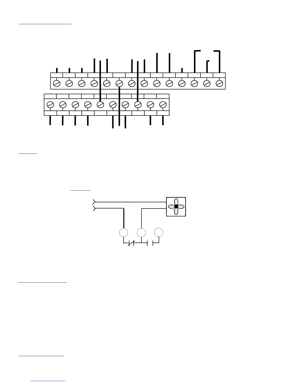
TERMINAL CONNECTIONS
:
NC C NO
RELAY
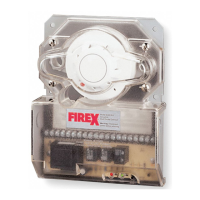
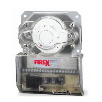
Firex Duct Unit
In alarm, 7 and 18
will open,
interrupting supply
to fan
18
8
Fan Supply Source
7
10A
ALARM
CONTACT
1
23456789
10
G
220
115
H
11
12 13 14 15
16 17
18 19
20
GROUND
24 VDC COM (-)
10A
*TROUBLE
CONTACTS
NO
POWER
INPUT
24
VAC/VDC
10A
ALARM
CONTACT
NC
NC
NO
C
C
POWER
INPUT
220/240
VAC
120
VAC
NC
NO
C
C
(+)
ALARM
CONTACT
L
(-) (+)
AUX
POWER
OUT
2A
ALARM
CONTACT
NO
*TROUBLE CONTACTS ARE SHOWN
IN NON-ENERGIZED CONDITION.
UNDER NORMAL OPERATION
CONTACTS WILL BE REVERSED.
TEST PROCEDURES
OPERATIONAL TESTING
To determine the correct operation of the Firex Duct Smoke Detector, ensure power is connected and the green pilot LED is illuminated.
The LED on the detector head flashes during the standby mode. The LED on the detector head will be permanently illuminated when smoke is
detected and the head is in alarm.
With the air handling unit shut down, and the clear cover removed, press and hold the test/reset button on the Firex Duct Unit. The red alarm
LED on the circuit board will be illuminated and the alarm relay outputs will change state. Using a multimeter set to OHMS (or continuity buzzer
function on the meter) place the meter probes on the following terminals and ensure the contacts are closed (continuity) (18, 8), (6,17) when
releasing the test/reset button these contacts will open.
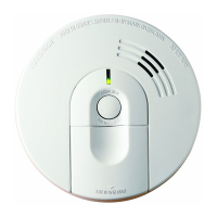
The trouble contacts (4, 15, 5) will not change state in the event of a fire alarm, operational or functional testing. The trouble contacts can be
tested by rotating the Apollo detector head counter-clockwise and removing the detector head. This action will extinguish the pilot (green) LED
and cause the trouble contacts to change state, (4, 15) will be closed (continuity) (5, 15) will be open circuit. Replacing the detector head and
rotating it clockwise until it locks, will cause the green pilot LED to be illuminated and the unit will be operational, terminals (4, 15) will be open
circuit and (5, 15) will be closed (continuity).
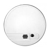
FUNCTIONAL TESTING
Once operational testing is concluded the unit requires functional testing to determine the correct operation of the detector head.
RESET INPUT
CAUTION:
For terminals (7, 8, 18), (6, 16, 17), (13, 14) do not use looped wire under terminals. Break wire run to provide supervision of connections. To
test the correct operation of the duct smoke unit, excluding the detector head (see functional testing page 4) remove detector head and connect
one of the appropriate dedicated power sources to the applicable terminals (See above). Replace detector head and the unit will be energized
(The green LED will be illuminated). When pressing the test/reset button the red alarm LED will be illuminated. In the event of a fire alarm,
certain equipment may have to be shut down. A shut down will be achieved by interrupting the supply source to that particular piece of equipment
when wired as indicated below.
EXAMPLE
:
FAN
AP 186 MA 2650-760; 01/01
 Loading...