10
GENERAL MAINTENANCE AND
ADJUSTMENTS SECTION
G
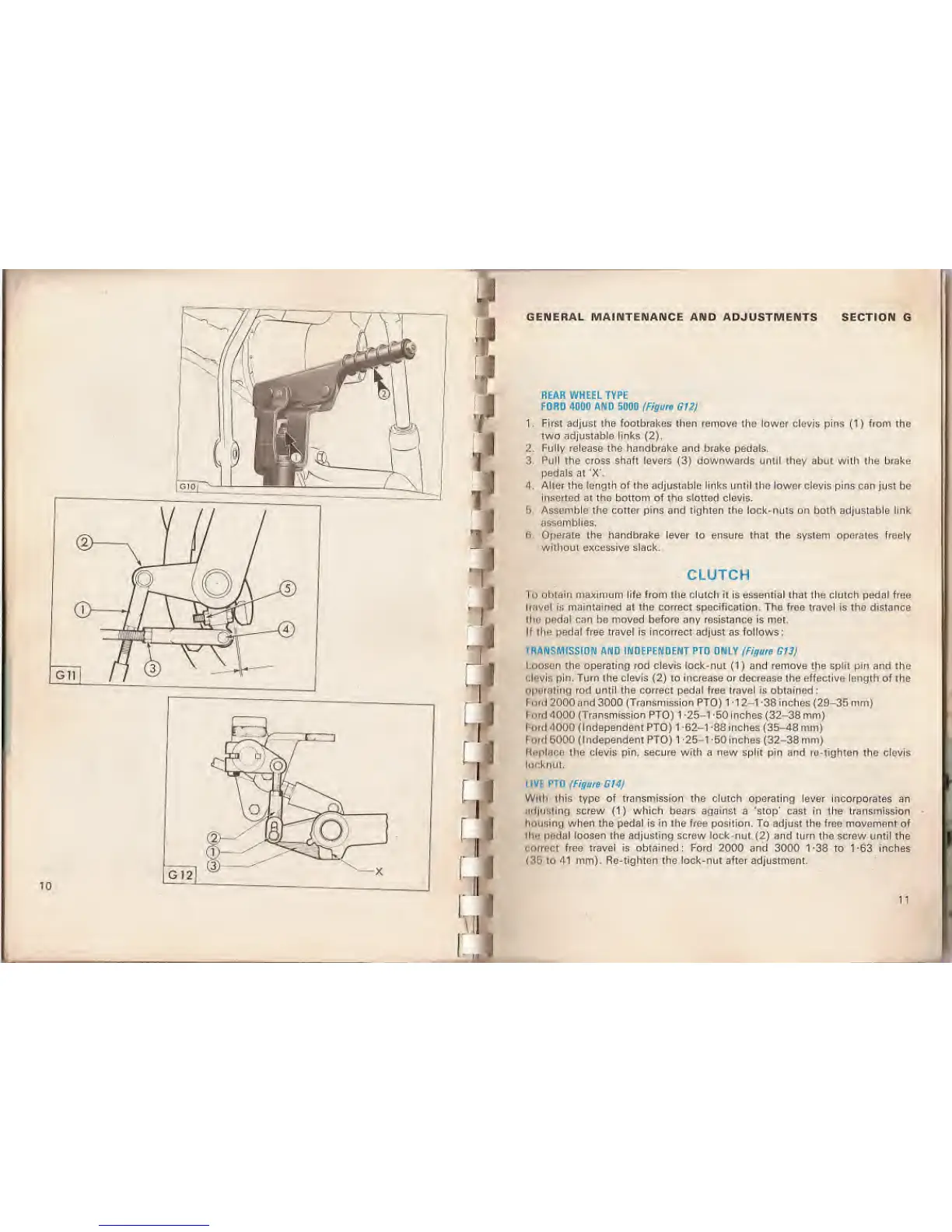
REAR WHEEL TYPE
FORD 4000 AND 5000 (Figure
G12)
1.
First adjust the footbrakes then remove the lower clevis pins
(1)
from the
two adjustable links
(2).
2.
Fully release the handbrake
and
brake
pedals,
3. Pull the cross shaft
levers
(3)
downwards until they abut with the brake
pedals
at 'X'.
4. Alter the length of the adjustable links until the lower clevis pins can
just be
inserted
at
the bottom of the slotted
clevis.
!> Assemble the cotter pins and tighten the lock-nuts on
both adjustable link
assemblies.
6. Operate the handbrake lever to ensure that the system operates freely
without excessive slack.
CLUTCH
To
obtain
maximum life from the clutch it is essential that the clutch pedal free
travel
is maintained at the correct specification. The froo travel
is
tho distance
the
pndal can be moved before any resistance is met.
If the pedal
free
travel is
incorrect
adjust as follows:
TRANSMISSION AND INDEPENDENT PTO ONLY (Figure G13j
Loosen the operating
rod clevis
lock-nut
(1)
and
remove
t)ie split pin and the
Clevis
pin. Turn the clevis
(2)
to increase or decrease the effective length of the
Operating rod until the correct pedal free travel is obtained:
I on I 2000 and 3000 (Transmission PTO) 1
-1 2-1 -38
inches (29-35 mm)
Ford 4000
(Transmission PTO)
1
-25-1
-50
inches
(32-38
mm)
Ford
-1000 (Independent
PTO)
1
-62-1
-88 inches (35-48
mm)
Ford 5000 (Independent PTO) 1
-25-1
-50
inches
(32-38
mm)
K.-i*i.ic:r ihu clevis pin,
secure with
a new spin pin and re lighten the clevis
looknut.
LIVE
PTO
(Figure G14)
Wnh
this type of
transmission
the clutch operating lever incorporates an
adjusting screw
(1)
which bears against a 'stop' cast in the transmission
housing when the pedal is in the free position. To adjust the froe movement of
tho pedal loosen the adjusting screw lock-nut
(2)
and turn the screw until
the
correct
free travel is obtained: Ford 2000 and
3000
1-38
to
1-63 inches
(35 to 41 mm).
Re-tighten
the
lock-nut
after adjustment.
11
 Loading...