----------PART
1 - ENGINE
SYSTEM----------
1
3
5
@
,
..
,,,
"-,
'
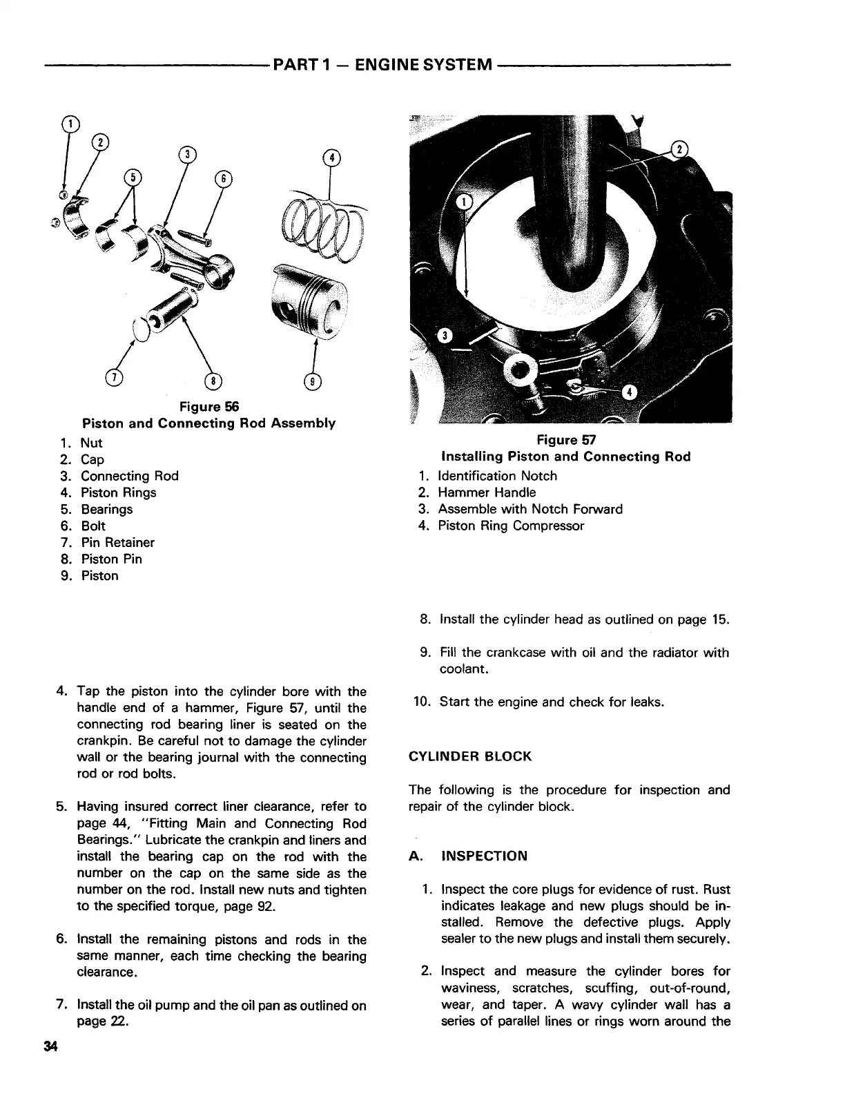
Figure
56
Piston and Connecting Rod Assembly
1.
Nut
2.
Cap
3. Connecting Rod
4. Piston Rings
5.
Bearings
6. Bolt
7. Pin Retainer
8. Piston Pin
9. Piston
4. Tap the piston into the cylinder bore with the
handle end
of
a hammer, Figure
57,
until the
connecting rod bearing liner is seated on the
crankpin.
Be
careful not
to
damage the cylinder
wall or the bearing journal with
the
connecting
rod or rod bolts.
5. Having insured correct liner clearance, refer
to
page 44,
"Fitting
Main and Connecting Rod
Bearings." Lubricate the crankpin and liners and
install the bearing cap on the rod
with
the
number on the cap on the same side
as
the
number on the rod. Install new nuts and tighten
to
the specified torque, page 92.
6. Install the remaining pistons and rods in the
same manner, each time checking the bearing
clearance.
7. Install the oil pump and the oil pan
as
outlined on
page 22.
34
Figure
57
Installing
Piston
and
Connecting
Rod
1.
Identification Notch
2. Hammer Handle
3.
Assemble with Notch Forward
4. Piston Ring Compressor
8.
Install the cylinder head
as
outlined on page
15.
9. Fill the crankcase with oil and the radiator
with
coolant.
10.
Start the engine and check
for
leaks.
CYLINDER BLOCK
The following
is
the procedure
for
inspection and
repair
of
the cylinder block.
A. INSPECTION
1.
Inspect the core plugs
for
evidence
of
rust. Rust
indicates leakage and new plugs should
be
in-
stalled. Remove the defective plugs. Apply
sealer
to
the new plugs and install them securely.
2. Inspect and measure the cylinder bores
for
waviness, scratches, scuffing, out-of-round,
wear, and taper. A wavy cylinder wall
has
a
series
of
parallel lines or rings worn around the
 Loading...


