--------------CHAPTER1-------------
LUBRICATION SYSTEM
A gear rotor-type oil pump, driven from the crankshaft
through
an
idler gear, is mounted on the
front
cover
plate.
It
takes oil from the deepest part
of
the oil pan
through
an
filter screen and pumps the oil into
the
lubrication system. A spring-loaded relief valve in the
pump body limits the maximum pressure in the system
by directing excess oil back
to
the intake side
of
the
pump.
Oil flows from the pump
to
a replaceable cartridge ex-
ternal filter. A relief valve in the filter permits oil
to
bypass a clogged filter, thereby maintaining oil
flow
to
the engine at all times.
Oil flows from the filter
to
the main oil gallery, which
runs
the
length
of
the cylinder block and intersects the
tappet chambers. The main oil gallery also supplies oil
to
all the crankshaft main bearings and
to
the connec-
ting rod journals by way
of
the crankshaft. Camshaft
bearings receive oil by means
of
drilled passages
from
the main bearings.
The camshaft drive gear bushing is pressure-lubricated
through a drilled passage from the
front
main bearing
and has spiral grooves
to
direct oil toward the outside
of
the gear. The gear has small oil passages machined
on both sides which allows the oil
to
exhaust. The tim-
ing gears
are
splash-lubricated from the pressure-
lubricated camshaft drive gear and the fuel injection
pump overflow.
Cylinder walls and pistons are splash-lubricated by the
crankshaft on the TW10. Piston pins
are
splash-
lubricated on the TW10; pressure-lubricated on the
TW20 and
30
tractors. An intermittent
flow
of
oil
is
fed
to
the valve rocker arm shaft assembly through a drill-
ed
passage in the cylinder block at the No. 1 camshaft
bearing which indexes with a hole in the cylinder head.
From the head, the oil flows up around the
No. 1
rocker arm support bolt
to
the rocker shaft. The oil
from the shaft flows through drilled holes in each
rocker arm
to
lubricate the valve end and the adjusting
screw end
of
the rocker arm.
Oil
from the ball ends
of
the rocker arms flows down the push rods and assists
in lubricating the tappets and push rods.
Excess
oil
drains into the push rod chamber through the push rod
holes in the cylinder head and then back
to
the oil pan
sump through cored openings in the block.
A heat exchange manifold is mounted on the left side
of
the engine block. The engine oil is cooled by water
as
it
is pumped through the exhange manifold.
Two
screw-on oil filters attached
to
the manifold filter the
engine oil.
2.
CYLINDER
HEAD,
VALVES
AND
RELATED
PARTS
The cylinder head can be removed from the engine
for
service
with the engine installed in the tractor.
A. REMOVAL
1.
Remove the pre-cleaner and the fuel tank cap.
2.
TW10 and
20:
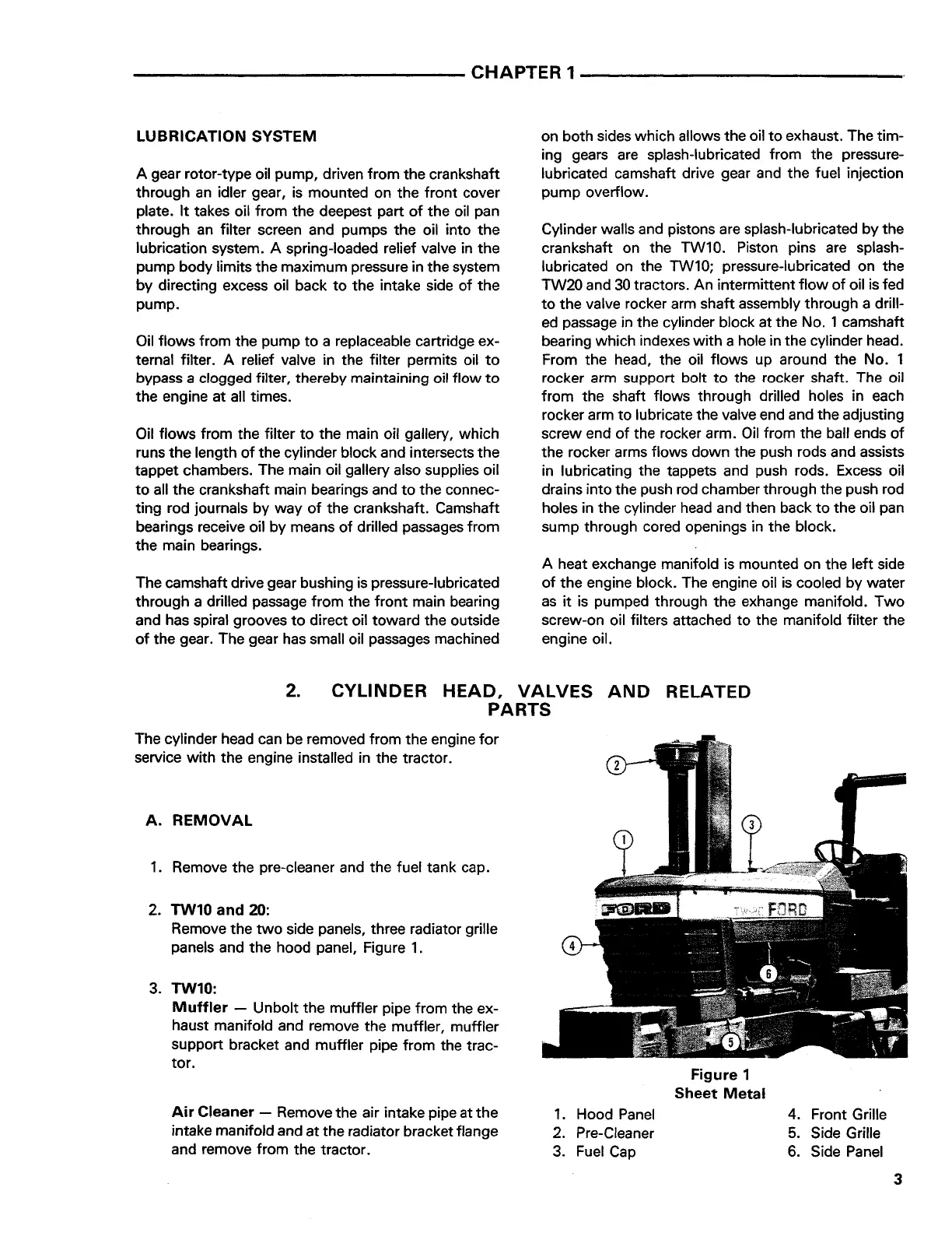
Remove the
two
side panels, three radiator grille
panels and the hood panel, Figure
1.
3. TW10:
Muffler
- Unbolt the muffler pipe from the ex-
haust manifold and remove the muffler, muffler
support bracket and muffler pipe from the trac-
tor.
Air Cleaner - Remove the air intake pipe at the
intake manifold and at the radiator bracket flange
and remove from the tractor.
1.
Hood
Panel
2. Pre-Cleaner
3.
Fuel
Cap
Figure 1
Sheet
Metal
4. Front Grille
5.
Side Grille
6.
Side Panel
3
Find manuals at https://best-manuals.comFind manuals at https://best-manuals.com
 Loading...


