Installation
Checklist for
installation
For installation information, see the following chapters:
1
Switch off the power supply before establishing a mains connection.
2
Mount the Fronius Smart Meter TS (see "Installation" on page 19).
3
Connect automatic circuit breakers or automatic circuit breakers and disconnectors
(see"Protective circuit" on page 19).
4
Connect the mains cable to the Fronius Smart Meter TS (see "Cabling" on page
20).
5
Connect the data communication connections of the Fronius Smart Meter TS to the
Fronius system monitoring using a suitable cable (see "Connecting the data com-
munication cable to the inverter" on page 21).
6
If necessary, set terminating resistors (see "Connecting the terminating resistor"
on page 22).
7
Tug on each wire and plug to make sure that they are securely connected to the ter-
minal blocks.
8
Switch on the power supply to the Fronius Smart Meter TS.
9
Check the firmware version of the Fronius system monitoring. To ensure compatibil-
ity between the inverter and the Fronius Smart Meter TS, the software must always
be kept up to date. The update can be started via the inverter web page or using
Solar.web.
10
If several Fronius Smart Meter TS are installed in the system, set the address (see
"Setting the address" under "Setting the address on the Fronius Smart Meter TS"
on page 27).
11
Configure and commission the meter (see Start-up on page 29).
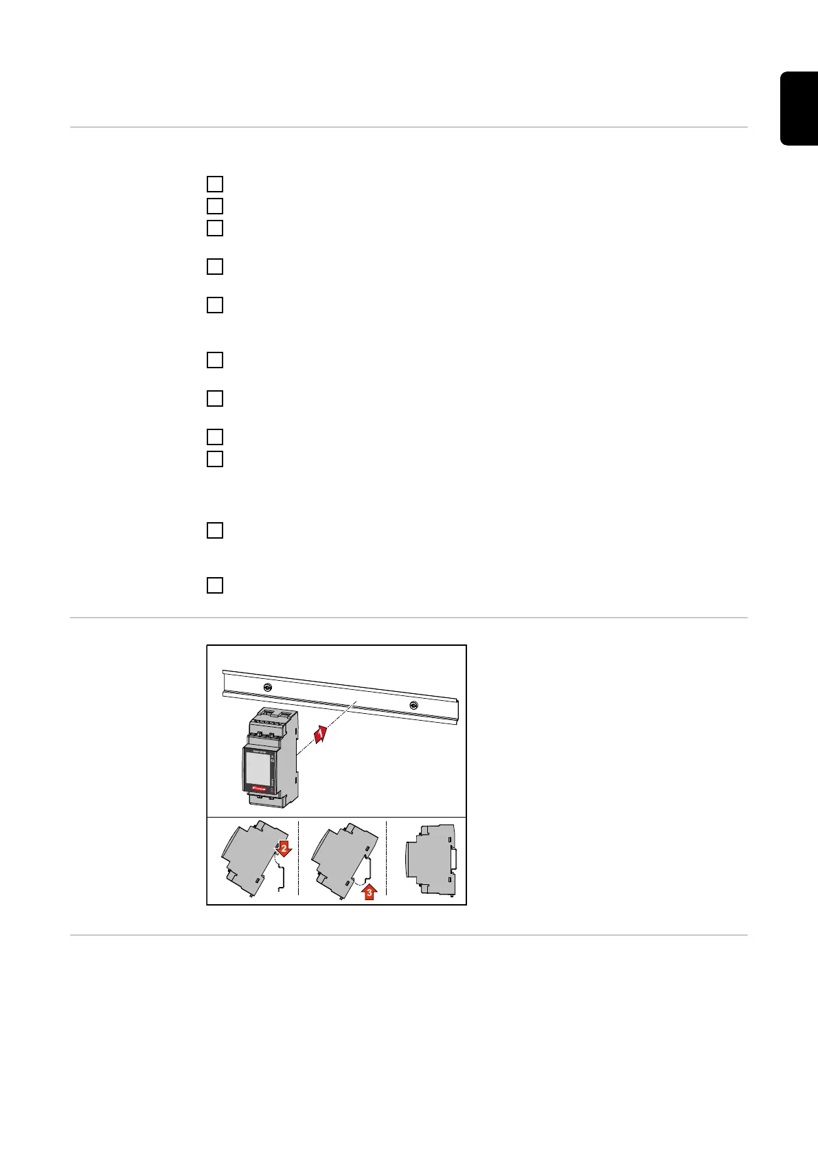
Installation The Fronius Smart Meter TS can be
mounted on a 35 mm DIN rail. The hous-
ing comprises 2 modules according to DIN
43880.
Protective circuit The Fronius Smart Meter TS is a hard-wired device and requires a disconnecting device
(circuit breaker, switch or disconnector) and overcurrent‑protection (automatic‑circuit
breaker).
The Fronius Smart Meter TS consumes 10 - 30 mA, the nominal capacity of the discon-
necting devices and the overcurrent‑protection is determined by the wire thickness, the
mains voltage and the required breaking capacity.
19
EN

 Loading...