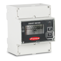
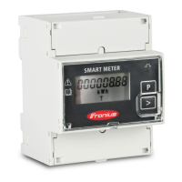
Location of the primary meter in the consumption branch. *Terminating resistor R 120 Ohm
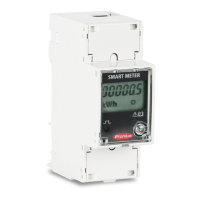
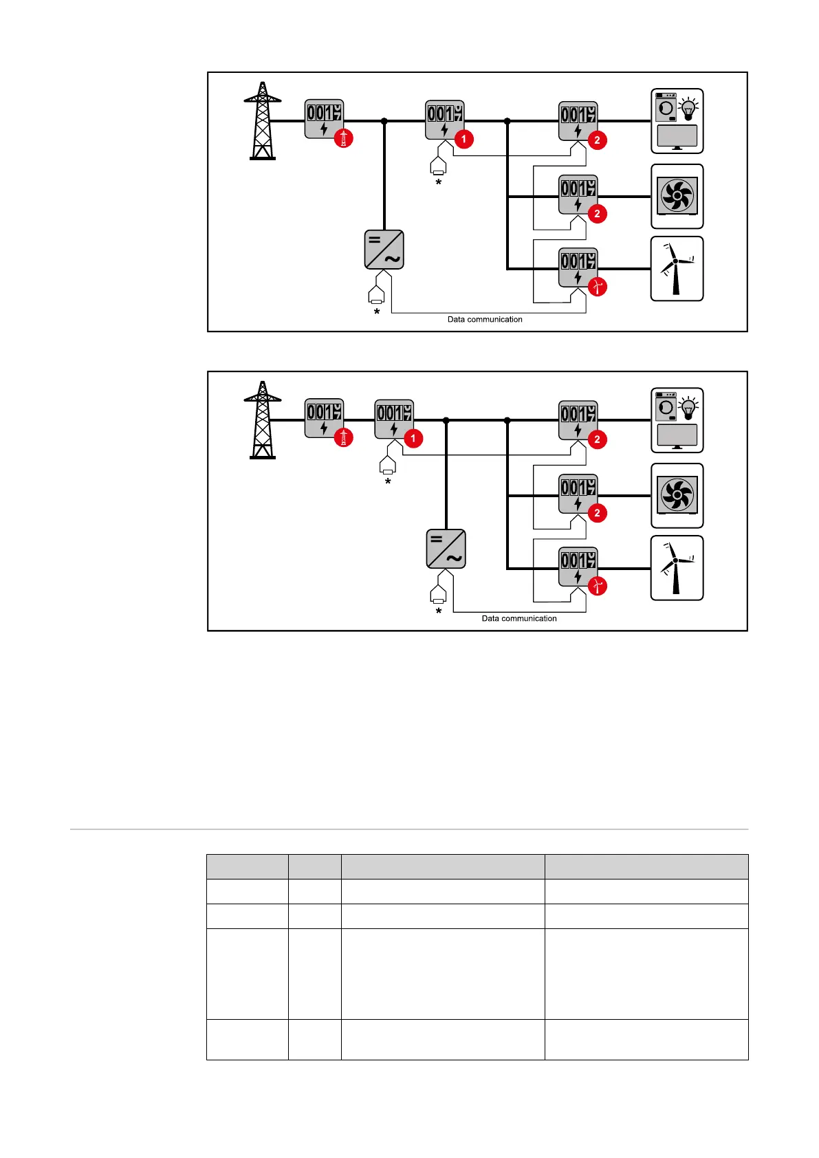
Location of the primary meter at the feed-in point. *Terminating resistor R 120 Ohm
The following must be observed in a multi-meter system:
- Only assign each Modbus address once.
- Terminating resistors must be positioned individually for each channel.
For PV systems with inverters from the Fronius GEN24 and Fronius Tauro product
series, the following must be observed:
- The primary meter and the battery must be connected to different channels.
- The remaining Modbus participants must be distributed equally.
Menu structure
and parameters
Screen Code Description Values
PASS*** P1 Enter the current password 2633*
nPASS P2 Password change ** Four digits (0000-9999)
MEASurE P3 Measurement mode ** A: easy connection, measures
all energy without taking the
direction into account.
B*: measures imported and
exported energy separately.
P int P4 Average power calculation
interval (minutes)
1* - 30
26

 Loading...