6
EN
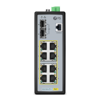
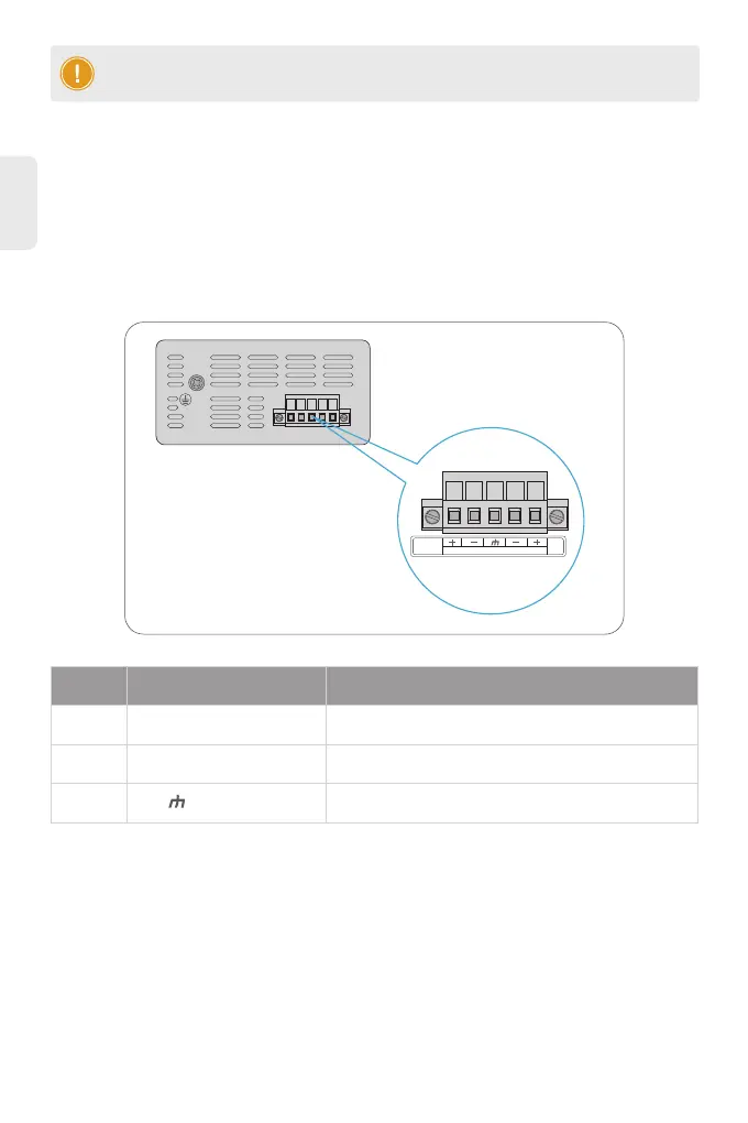
The Upper Panel of the switch indicates a DC inlet power socket and consists of one terminal block
connector within 5 contacts. Please follow the steps below to insert the power wire.
1. Insert positive/negative DC power wires into Contacts + and - for Power 1 and Power 2.
2. Tighten the wire-clamp screws for preventing the wires from loosening.
Connecting the Power
NOTE: This product is intended to be mounted to a well-grounded mounting surface such
as a metal panel.
PWR1
48-57V DC
PWR2
Live line/Positive
Null line/Negative
Requiring good ground connection
NameNo. Description
L/+
N/-
1
2
3
 Loading...