25G
1 2
3 4
22 2423
40G Breakout
25
26
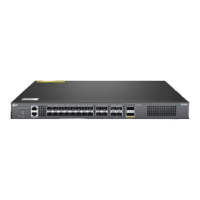
S5860-20SQ
40G
MGMT
CONSOLE
25G
STATUSPWR1 PWR2 FAN MGMT ID
1 2
3 4
21
43 65 87 109 1211 1413 1615
1817 2019 2221 2423
40G Breakout
25
26
40G
FUNC
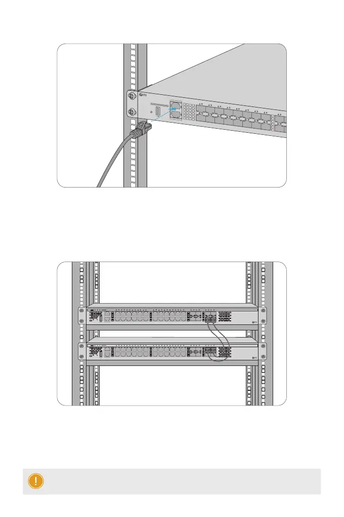
1. Connect one end of a standard RJ45 Ethernet cable to a computer.
2. Connect the other end of the cable to the MGMT port on the switch.
Connecting the MGMT Port
Stacking the Switches
MGMT
SYS PWR FAN
PoE
1 2
3
4
5
6 7 8
9 10
11 12
13 14 15 16 17 18 19 20 21 22
23 24
25 26
27 28
29 30
31 32
PoE FUNC
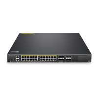
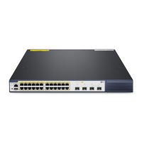
S5860-24XB-U
Green=10G/5G/2.5G/1G On=Link Flashing=ACT
PoE LED Mode:Green=Good Supply
Yellow=Over Load
CONSOLE
Yellow=100M
MGMT
SYS PWR FAN
PoE
1 2
3
4
5
6 7 8
9 10
11 12
13 14 15 16 17 18 19 20 21 22
23 24
25 26
27 28
29 30
31 32
PoE FUNC
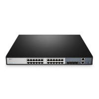
S5860-24XB-U
Green=10G/5G/2.5G/1G On=Link Flashing=ACT
PoE LED Mode:Green=Good Supply
Yellow=Over Load
CONSOLE
Yellow=100M
The S5860 series switches support stacking up to 2 switches between the same models together.
The switch can be physically stacked using optical ber cables connected to SFP+/SFP28 transceivers
or 10/25G Direct Attach Cables (DAC). Any two SFP+/SFP28 ports on the switch can be used for
physical stacking. The copper ports can also be used for physical stacking.
NOTE: S5860-20SQ/S5860-24XB-U switches support stacking with each other.
 Loading...