En-7
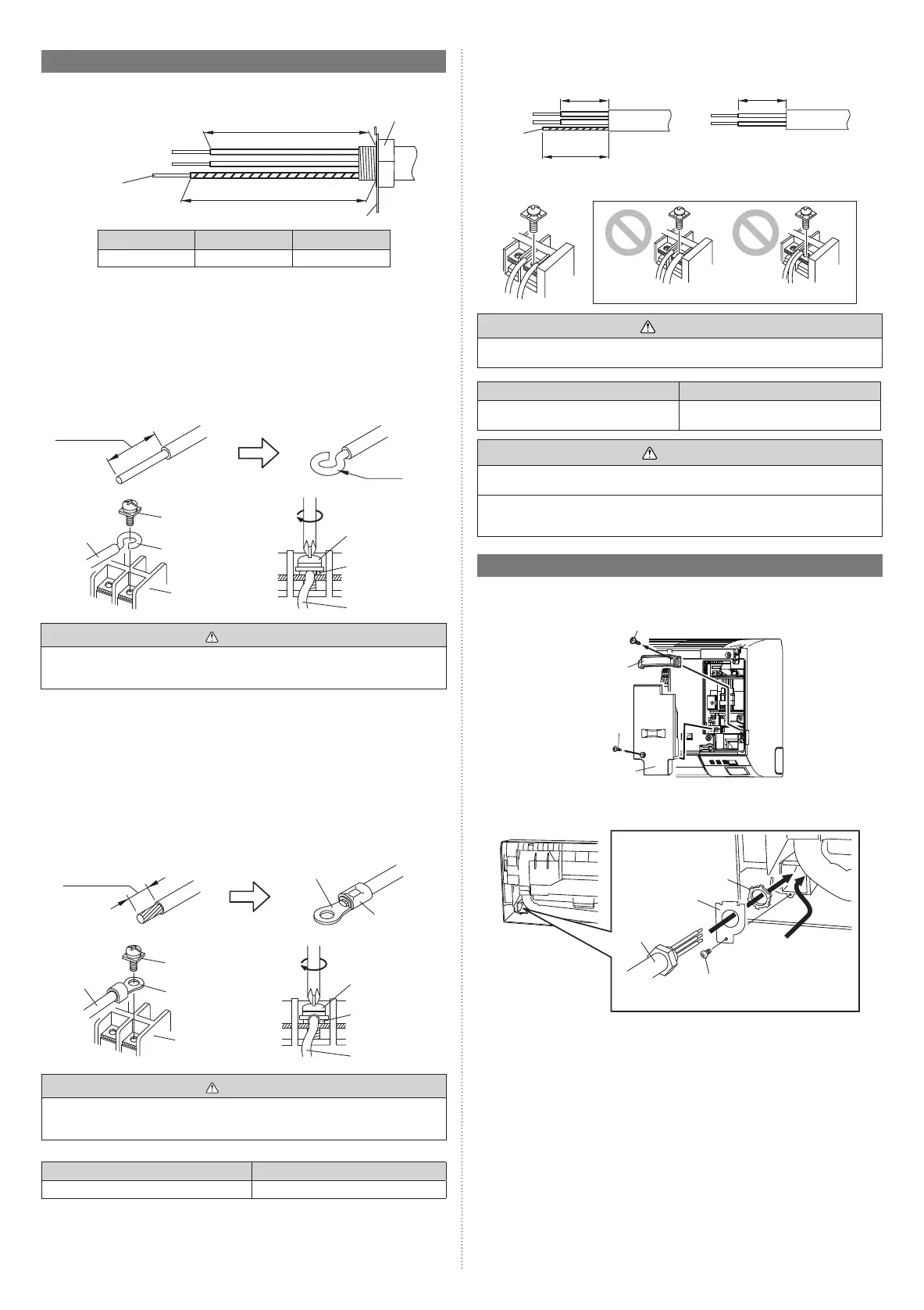
5.3. Unit wiring
• Before attaching the cable to terminal block.
5.3.1. Power supply cable
A
B
Conduit connector
Conduit holder
Earth
(ground) cable
A [in (mm)] B [in (mm)]
30/36 model 9-7/16 (240) 10-1/4 (260)
A. For solid core wiring
(1) To connect the electrical terminal, follow the below diagram and connect after looping
it around the end of the cable.
(2) Use the specified cables, connect them securely, and fasten them so that there is no
stress placed on the terminals.
(3) Use an appropriate screwdriver to tighten the terminal screws. Do not use a screw-
driver that is too small, otherwise, the screw heads may be damaged and prevent the
screws from being properly tightened.
(4) Do not tighten the terminal screws too much, otherwise, the screws may break.
(5) See the table for the terminal screw tightening torques.
(6) Please do not fix 2 power supply cables with 1 screw.
Strip 1 in
(25 mm)
Screw with
special washer
Screw with
special washer
Cable end (Loop)
Loop
Terminal block
Cable end (Loop)
Cable
Cable
WARNING
When using solid core cables, do not use the attached ring terminal. If you use the solid
core cables with the ring terminal, the ring terminal's pressure bonding may malfunction
and cause the cables to abnormally heat up.
B. For strand wiring
(1) Use ring terminals with insulating sleeves as shown in the figure below to connect to
the terminal block.
(2) Securely clamp the ring terminals to the cables using an appropriate tool so that the
cables do not come loose.
(3) Use the specified cables, connect them securely, and fasten them so that there is no
stress placed on the terminals.
(4) Use an appropriate screwdriver to tighten the terminal screws. Do not use a screw-
driver that is too small, otherwise, the screw heads may be damaged and prevent the
screws from being properly tightened.
(5) Do not tighten the terminal screws too much, otherwise, the screws may break.
(6) See the table for the terminal screw tightening torques.
(7) Please do not fix 2 power supply cables with 1 screw.
Strip 3/8 in
(10 mm)
Ring terminal
Sleeve
Screw with
special washer
Screw with
special washer
Ring terminal
Terminal block
Ring terminal
Cable
Cable
WARNING
Use ring terminals and tighten the terminal screws to the specified torques, otherwise,
abnormal overheating may be produced and possibly cause heavy damage inside the
unit.
Terminal number Tightening torque
M4 screw (Power supply/L1, L2(N), GND) 11 to 16 lbf·in (1.2 to 1.8 N·m)
5.3.2. Transmission and Remote controller cable
Transmission cable Remote controller cable
Shield
cable
(no film)
13/16 in (20 mm)
1-3/8 in
(35 mm)
13/16 in (20 mm)
• Connect remote controller and transmission cables as shown in figure below.
GOOD
Different diameter
Connect to 1 side
PROHIBITED
WARNING
Tighten the terminal screws to the specified torques, otherwise, abnormal overheating
may be occurred and possibly cause serious damage inside the unit.
Terminal number Tightening torque
M3 screw (Transmission /X1, X2)
(Remote controller /Y1, Y2)
4.4 to 5.3 Ibf·in (0.5 to 0.6 N·m)
CAUTION
To peel the sheath from the lead cable, use a dedicated tool that will not damage the
conductor cable.
When installing a screw on the terminal block, do not cut the wire by overtightening the
screw. On the other hand, an under tightened screw can cause faulty contact, which will
lead to a communication failure.
5.4. Wiring
(1) Open the intake grille. Refer to “8. FRONT PANEL REMOVAL AND INSTALLATION”.
(2) Remove the wire cover and remove the cable clamp.
Screw
Screw
Cable
clamp
Wire cover
(3) Remove the conduit holder.
(4) Fasten the indoor unit wire harness to the conduit holder using the lock nut.
(5) Use the screws to install the conduit holder provide with the indoor unit.
Screw
Conduit holder
Conduit
connector
• Transmission cables
• Wired remote controller
cable and optional parts
cables (if necessary)
Lock nut
9373370475-01_IM.indb 79373370475-01_IM.indb 7 9/16/2019 2:31:27 PM9/16/2019 2:31:27 PM
 Loading...