En-8
5.5.3. Connection methods
Wire modification
(1) Remove insulation from wire at-
tached to wire kit connector.
(2) Remove insulation from field
supplied cable. Use crimp type
insulated butt connector to join field
cable and wire kit wire.
(3) Connect the wire with connecting
wire with solder.
IMPORTANT:
Be sure to insulate the connection between the
wires.
Locally
purchased
Solder and insulate the connected parts.
Wire kit connector
(optional parts)
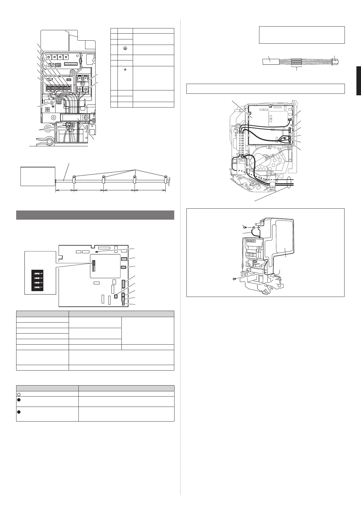
Wiring arrangement
In following figure, all the possible connectors are connected for description.
In actual installation, you cannot connect all the connectors at once.
CNA02
CNA01
CNA03
CNA04
CNB01
CN65
Controller PCB
Connecting cables
When replacing the control box cover, be sure to attach the wire with the screw.
Wire
Control box
cover
Screw
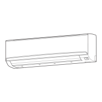
(6) Connect the end of the connection cable fully into the terminal block.
D
A
E
B
F
C
G
H
I
L1 L2
X1 Y1 Y2 Y3X2
Cable tie
(acces-
sories)
Cable
clamp
Symbol Connection cable
A
L1 Power supply cable
B
L2
C
Earth (ground) for
power supply cable
D
X1 Transmission cable
E
X2
F
Earth (ground) for
transmission cable
and wired remote
controller cable (if
necessary)
G
Y1 Wired remote control-
ler cable (nonpolar)
H
Y2
I
Y3 Do not use
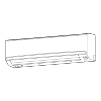
(7) Fix the conduit with the supporters as shown below.
Conduit (power supply cable)
Indoor unit
Supporter
30 in
(756 mm)
or less
54 in
(1,361 mm)
or less
54 in
(1,361 mm)
or less
54 in
(1,361 mm)
or less
5.5. Optional parts wiring
In this setting, you need to remove the front panel. Refer to “8. FRONT PANEL REMOVAL
AND INSTALLATION”.
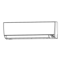
5.5.1. Connector and DIP switch position
CNA02
CNA01
CNA03
CNA04
CNB01
CN65
CN820
SW1
SW2
SW3
SW4
Power indicator
lamp (green)
DIP switch
(SET 2)
ON OFF
Controller PCB
Name Application
CNA01
Apply voltage terminal For external input
CNA03
CNA02 Dry contact terminal
CNA04
DIP switch SET 2 (SW2) Input signal type switching
CNB01 Output terminal For external output
CN65 For one of the following.
• MODBUS® convertor (*1)
• Wireless LAN adapter (*1)
CN820 For External power supply unit (*1)
*1: For details, refer to each installation manual.
5.5.2. Power indicator lamp status
Power indicator lamp (Green) Status contents
Lit
Lit when the power is turned on.
Fast flashing (every 0.1
second)
There is a fault with the communication board or the
main board.
Blinking (repeat 3 seconds ON
and 1 second OFF)
The indoor unit is turned off and power is supplied
from the External power supply unit (optional) to the
indoor unit PCB.
9373370475-01_IM.indb 89373370475-01_IM.indb 8 9/16/2019 2:31:27 PM9/16/2019 2:31:27 PM
 Loading...