En-6
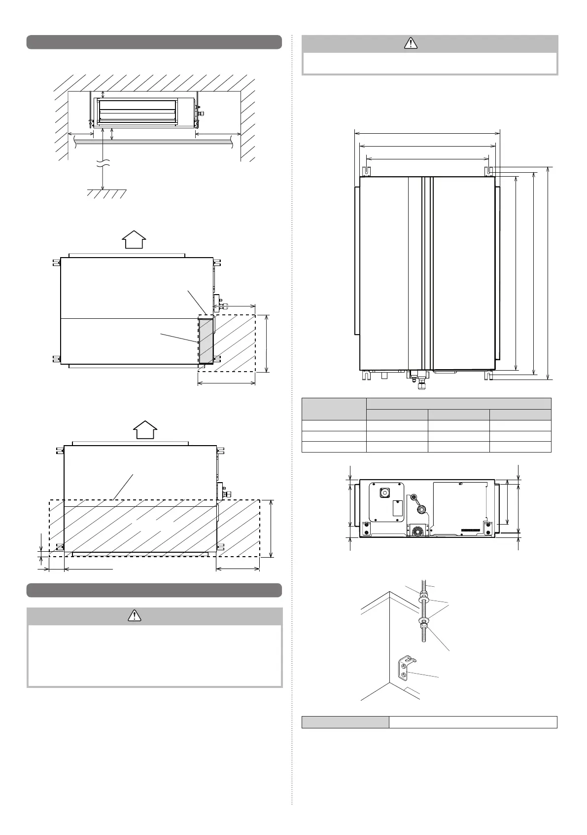
3. 2. Installation dimension
Unit: mm
150 or
more
300 or more
2500 or more
(When no ceiling)
20 or more
20 or more
Provide a service access for maintenance purposes.
(Bottom side) Unit: mm
AIR
Control box
300 or more
500 or more
500 or more
Service access
* The service access necessary for fan units and fi lter maintenance.
(Bottom side) Unit: mm
AIR
Service access
Fan unit side
300 or more
500 or more
100 or more
100
3. 3. Installing the unit
WARNING
• Carrying and installation of the unit should be performed by a suffi cient number
of people and with suffi cient equipment that is adequate for the weight of the unit.
Performing such work with an insuffi cient number of people or with inadequate
equipment could result in dropping of the unit or personal injury.
• If the job is done with the panel frame only, there is a risk that the unit will come
loose. Please take care.
• When fastening the hangers, make the bolt positions uniform.
CAUTION
Confi rm the directions of the air intake and outlet before installing the unit.
The unit takes in air from the evaporator side, and expels it from the fan side.
3. 3. 1. Position the ceiling hole
Hanging bolt installation diagram.
Unit: mm
(Top side)
750
700
630
A
B
C
Model
Dimension (mm)
AB
C
12/14 700 740 800
18/22/24/30 1000 1040 1100
36/45/54 1400 1440 1500
(Right side)
57
22
218
256
222
25
22
3. 3. 2. Body installation
Hanging bolt M10
(Locally purchased)
Special nut A
(Accessory)
Washer
(Accessory)
Hanger
Special nut B
(Accessory)
Bolt Strength 9.81 to 14.71 N·m (100 to 150 kgf·cm)
9381386215-01_IM.indb 69381386215-01_IM.indb 6 12/5/2018 2:57:36 PM12/5/2018 2:57:36 PM
 Loading...