En-13
(4) Seal the cable outlet or other gaps with putty to prevent dew condensation or insect
from entering the electric control box.
(5) Replace the control box cover.
CAUTION
Do not bundle the remote controller cable, or wire the remote controller cable in par-
allel, with the indoor unit connection wire (to the outdoor unit) and the power supply
cable. It may cause erroneous operation.
3.7. Remote controller setting
To install and set the remote controller, refer to the installation manual of the remote
controller.
4. OPTIONAL INSTALLATION WORK
4.1. Optional kit installation
WARNING
Regulation of cable differs from each locality, refer in accordance with local rules.
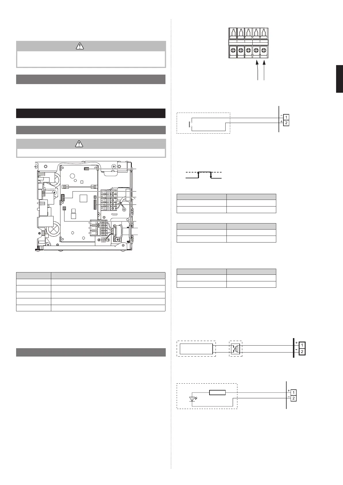
Y1 Y2
TO REMOTE CONTROL UNIT Ex IN
Y3 1 2
12 3
CN65
CN11
CN47
CN48
CN8
This air conditioner can be connected with the following optional kits.
For details on how to install optional parts, refer to the installation manual included in each
item.
Connector No. Option type
CN47*1 Connect wire (UTY-XWZXZG)
CN8 Remote sensor (UTY-XSZX)
CN48 IR Receiver (UTY-LBTM)
CN11 Auto louver grille (UTD-GXT-W)
CN65*2 Other optional parts
*1: For external output terminal setting, refer to Function No.60 in “6. FUNCTION SET-
TING”.
*2: Other options (WLAN adapter, converters, etc.) may be connectable. Please refer to
the technical data for details.
NOTES:
Options connecting to CN65 cannot be used at the same time.
4.2. External input and output
4.2.1. External input
• Indoor unit functions such as Operation/Stop or Forced stop can be done by using
indoor unit terminals.
• “Operation/Stop” mode or “Forced stop” mode can be selected with function setting of
indoor unit.
•
A twisted pair cable (22 AWG) should be used. Maximum length of cable is 150 m (492 ft.).
• Use an external input and output cable with appropriate external dimension, depending
on the number of cables to be installed.
• The wire connection should be separate from the power cable line.
Y1 Y2
TO REMOTE CONTROL UNIT Ex IN
Y3 1 2
Connected device
Terminal
● Dry contact terminal
When a power supply is unnecessary at the input device you want to connect, use the Dry
contact terminal.
*1
Terminal
(External in)
Connected device
*1: The switch can be used on the following condition: DC 12 V to 24 V, 1 mA to 15 mA.
■
Operation behavior
● Input signal type
Edge
ON
OFF
When function setting is “Operation/Stop” mode 1.
Input signal Command
OFF → ON Operation
ON → OFF Stop
When function setting is “Forced stop” mode.
Input signal Command
OFF → ON Forced stop
ON → OFF Normal
* When the forced stop is triggered, indoor unit stops and Operation/Stop operation by a
remote controller is restricted.
When function setting is “Operation/Stop” mode 2.
Input signal Command
OFF → ON Operation
ON → OFF Stop (R.C. disabled)
4.2.2. External output
• A twisted pair cable (22AWG) should be used. Maximum length of cable is 25 m (82 ft.).
• Use an external input and output cable with appropriate external dimension, depending
on the number of cables to be installed.
• Output voltage: Hi DC12V±2V, Lo 0V.
• Permissible current: 50mA
■
Output select
When interlocking with external device
CN47
PCB
Connected
device
Relay (locally purchased)
or
When displaying “Operation/Stop”
CN47
PCB
Connected device
Resistor
LED
9374342532_IM.indb 139374342532_IM.indb 13 2018/12/11 10:11:352018/12/11 10:11:35
 Loading...