En-15
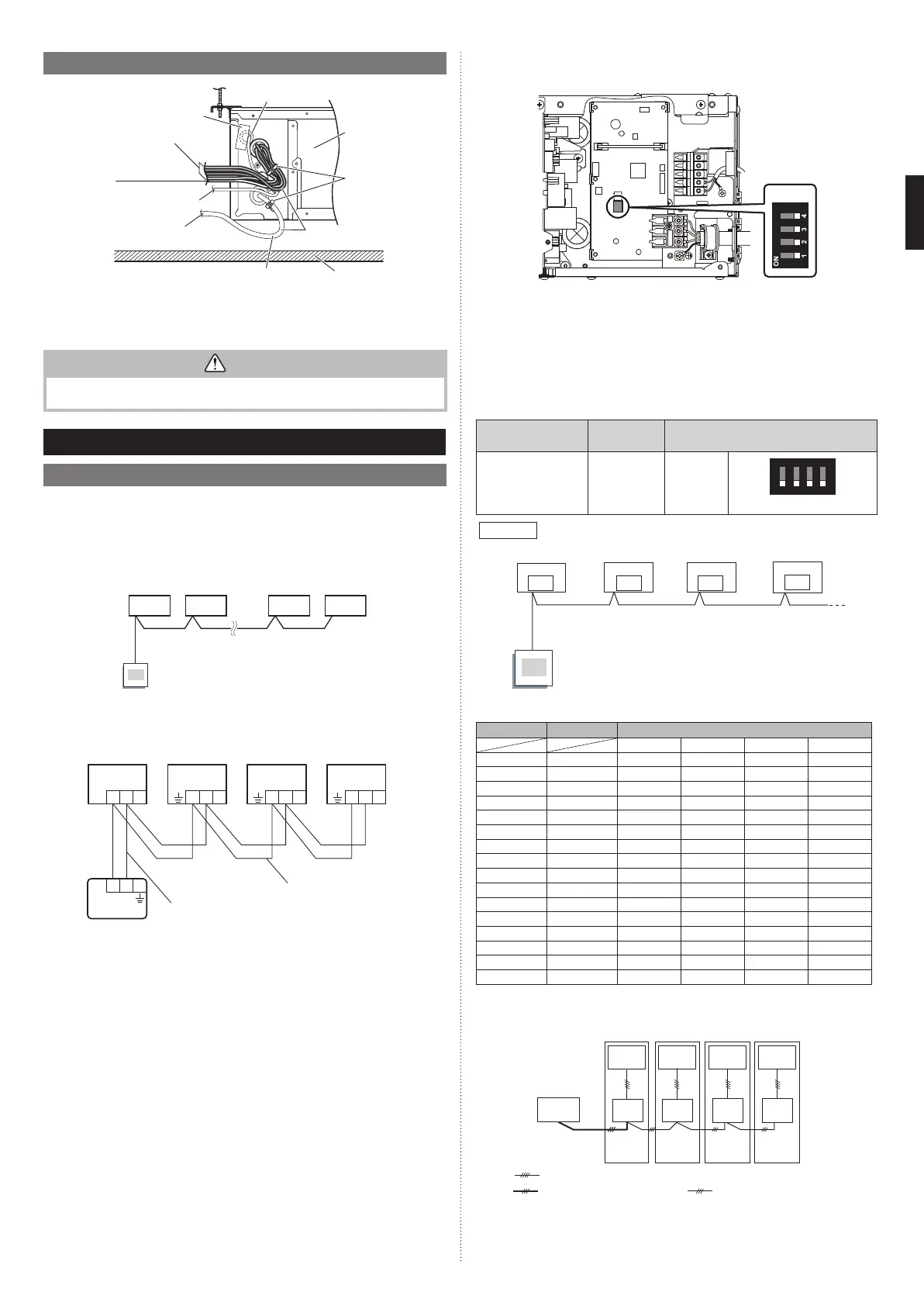
4.7. Optional parts cable binding
Auto louver grille cable
Remote controller
cable
Other optional parts cables
Power supply cable
Avoid touching the ceiling with the wirings.
* Use an accessory of indoor unit or optional parts for cable tie.
** Use an accessory of optional parts for bushing.
Ceiling
Cable tie
(medium,
accessories)
Avoid covering the air
inlet with the wirings.
Air inlet
Bushing**
Insulation
• Do not bind the power supply cable and other cables together.
CAUTION
To protect the cable insulation after opening a knockout hole, remove any burrs from
the edge of the hole.
5. REMOTE CONTROL INSTALLATION
5.1. Group control
NOTES: Group control cannot be used together with W-LAN adapter.
A number of indoor units can be operated at the same time using a single remote controller.
*When different types of indoor units (such as wall mounted type and cassette type, cas-
sette type and duct type, or other combinations) are connected using group control sys-
tem, some functions may no longer be available.
(1) Connect up to 16 indoor units in a system.
A
BCDE
I.U. I.U. I.U. I.U.
Remote
controller
A, B, C, D, E : Remote controller cable.
A+B+C+D+E ≤ 500 m.
Example of wiring method (2-wire type)
123 123 123 123
123
Y
1 Y2
Indoor unit 1 Indoor unit 2 Indoor unit 3 Indoor unit 4
Remote controller cable
Remote con-
troller cable
Remote controller
(2) Set the R.C. address (DIP switch setting)
Set the R.C. address of each indoor unit using the DIP switch on the indoor unit
circuit board.
Y1 Y2
TO REMOTE CONTROL UNIT Ex IN
Y3 1 2
12 3
SW100
(a) 2-wire type
DIP switch (RC AD SW)...Factory setting “00”
Since the remote controller address settings are automatically confi gured, you do not
need to confi gure them.
If confi guring manually, it is necessary to confi gure both the indoor unit and the remote
controller. For details, please refer to the remote controller installation manual.
(b) 3-wire type
DIP switch (RC AD SW)...Factory setting “00”
When connecting multiple indoor units to 1 standard wired remote controller, set the
address at RC AD SW in sequence from “00”.
Setting
Setting
range
Switch 100
Remote controller
address
00 to 15
Setting
example 00
1234
ON
RC AD
Example
If 4 indoor units are connected.
RC AD SW
00
RC AD SW
01
RC AD SW
02
RC AD SW
03
Indoor unit 1
Remote
controller
Indoor unit 2 Indoor unit 3 Indoor unit 4
Set the R.C. address in accordance with the table below.
Indoor unit
R.C. address
DIP SWITCH No.
1234
1 00 OFF OFF OFF OFF
2 01 ON OFF OFF OFF
3 02 OFF ON OFF OFF
4 03 ON ON OFF OFF
5 04 OFF OFF ON OFF
6 05 ON OFF ON OFF
7 06 OFF ON ON OFF
8 07 ON ON ON OFF
9 08 OFF OFF OFF ON
10 09 ON OFF OFF ON
11 10 OFF ON OFF ON
12 11 ON ON OFF ON
13 12 OFF OFF ON ON
14 13 ON OFF ON ON
15 14 OFF ON ON ON
16 15 ON ON ON ON
NOTES:
Be sure to set consecutive R.C. address.
The indoor units cannot be operated if a number is skipped.
00 01 02 03
R.C. address
(DIP switch setting)
Remote
controller
: Transmission cable, Power supply cable
: Connection cable
: Remote controller cable
Outdoor
unit 1
Indoor
unit 1
Indoor
unit 2
Indoor
unit 3
Indoor
unit 4
Outdoor
unit 2
Outdoor
unit 3
Outdoor
unit 4
9374342532_IM.indb 159374342532_IM.indb 15 2018/12/11 10:11:362018/12/11 10:11:36
 Loading...