En-3
• Do not use the unit for special purposes, such as storing food, raising animals, grow-
ing plants, or preserving precision devices or art objects.
• It can degrade the quality of the preserved or stored objects.
• Do not install where there is the danger of combustible gas leakage.
• Do not install the unit near a source of heat, steam, or fl ammable gas.
• Install the unit where drainage does not cause any trouble.
• Install the indoor unit, outdoor unit, power supply cable, transmission cable, and re-
mote control cable at least 1 m away from a television or radio receivers. The purpose
of this is to prevent TV reception interference or radio noise.
• (Even if they are installed more than 1 m apart, you could still receive noise under
some signal conditions.)
• If children under 10 years old may approach the unit, take preventive measures so
that they cannot reach the unit.
• Install the indoor unit on the wall where the height from the fl oors more than 1800 mm.
6. INSTALLATION WORK
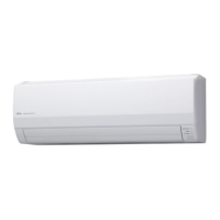
6.1. Installation dimensions
70 mm or over
1.5 m or over
Remote
controller
Remote controller holder
Tapping screw (small)
1.8 m
or over
(Wallcap)
63 mm or over
Wall hook
bracket
130 mm or over
6.2. Indoor unit piping direction
The piping can be connected in the
6
directions indicated in the following.
When the piping is connected in direction
2
,
3
,
4
or
5
,
cut along the piping groove in
the side of the front cover with a hacksaw.
2
Right
outlet
5
Left
outlet
6
Left rear
outlet
3
Bottom outlet
1
Rear outlet
4
Left bottom outlet
(Rear)
6.3.
Cutting the hole in the wall for the connecting piping
(1) Cut a 65 mm diameter hole in the wall at the position shown in the following.
(2) Cut the hole so that the outside end is lower (5 to 10 mm) than the inside end.
(3) Always align the center of the wall hole. If misaligned, water leakage will occur.
(4)
Cut the wall pipe to match the wall thickness, stick it into the wall cap, fasten the cap with
vinyl tape, and stick the pipe through the hole.
(5) For left piping and right piping, cut the hole a little lower so that drain water will fl ow
freely.
Wall
Fasten with
vinyl tape
65 mm dia. hole
65 mm dia. hole
Wall hook bracket
Center mark
Center mark
Wall cap*
Wall pipe*
(Inside)
(Outside)
5 to 10 mm low
*Field supplied
WARNING
If the wall pipe is not used, the cable interconnecting the indoor unit(s) and outdoor unit
may touch metal and cause electric discharge.
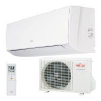
6.4. Installing the wall hook bracket
• Remove the wall hook bracket from the indoor unit. (Remove 2 screws).
(1) Install the wall hook bracket so that it is correctly positioned horizontally and vertically.
If the wall hook bracket is titled, water will drip to the fl oor.
(2)
Install the wall hook bracket so that it is strong enough to support the weight of the unit.
•
Fasten the wall hook bracket to the wall with 5 or more screws through the holes near the
outer edge of the bracket.
•
Check that there is no rattle at the wall hook bracket.
Wall hook bracket
Tapping screw
CAUTION
Install the wall hook bracket both horizontally and vertically aligned. Misaligned installa-
tion may cause water leakage.
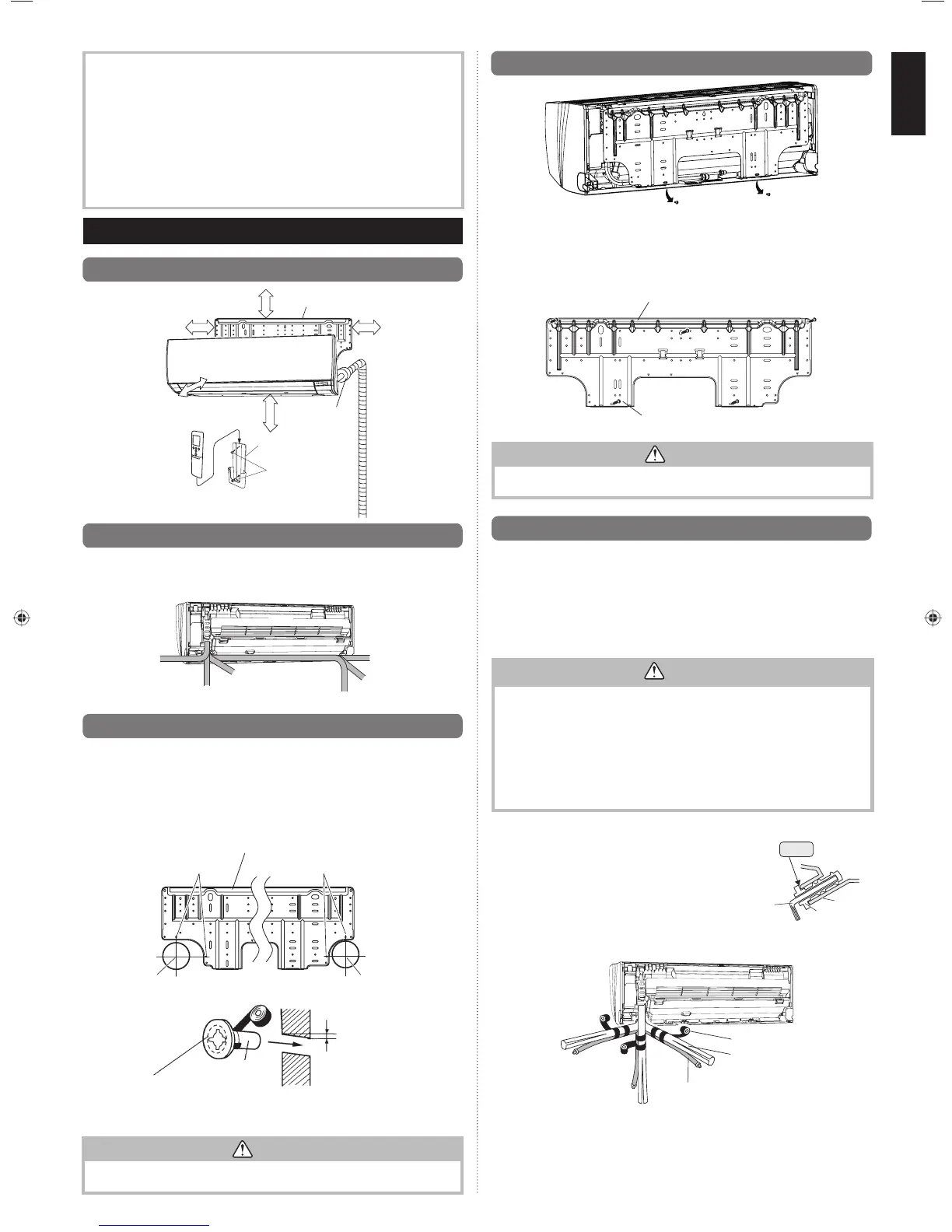
6.5.
Forming the drain hose and pipe
[Rear piping, Right piping, Bottom piping]
• Install the indoor unit piping in the direction of the wall hole and bind the drain hose
and pipe together with vinyl tape.
• Install the piping so that the drain hose is at the bottom.
• Wrap the pipes of the indoor unit that are visible from the outside with decorative tape.
[For Left rear piping, Left piping]
Interchange the drain cap and the drain hose.
CAUTION
• Insert drain hose and drain cap securely. Drain should slope down to avoid water leakage.
• When inserting, be sure not to attach any material besides water. If any other
material is attached, it will cause deterioration and water leakage.
• After removing drain hose, be sure not to forget mounting drain cap.
• Be sure to fi x the drain hose with tape to the bottom of piping.
•
Prevent drain water freezing under low temperature environment.
When installing indoor unit’s drain hose outdoors, necessary measure for frost
protection should be taken to prevent drain water freezing.
Under low temperature environment (when outdoor temperature under 0 °C), after
cooling operation is executed, water in the drain hose could be frozen. Once drain water
is frozen, the drain hose will be blocked and water leakage may result at the indoor unit.
Installation method of Drain cap
Use a hexagonal wrench 4 mm at opposite side to insert
the drain cap, till the drain cap contacts the tip of drain
cock.
Right piping
Bottom piping
Bind with vinyl tape
Refrigerant pipes (top)
Rear piping
Indoor unit drain hose (bottom)
No gap
Hexagonal
wrench
Drain
cock
Drain cap
9333005072_IM.indb 39333005072_IM.indb 3 2013-9-24 11:44:172013-9-24 11:44:17
 Loading...