En-7
(7)
(5)
(5)(6)Cover
Detail view
13.3.
Installing communication box
13.3.1. Removing intake grille
( Refer to 9.1. Front panel removal )
13.3.2. Removing control box
(1) Remove the screws (x4). (Use the same screws when installing.)
(2) Pull the control box cover towards you and remove.
(1)
(1)
(2)
(1)
(1)
(3) Remove the connectors (x4).
• Remove and pull off the lock at the side of the connector insertion part.
CAUTION
• Be careful not to damage the parts on the board.
Otherwise, it will cause malfunction.
Connector number: CN 5
Connector number: CN 4
Connector number: CN 3
Connector number: CN 7
* : Symbol indicating the location printed on the board
(4) Remove the wires from the three fixtures. (See the figure below)
• Leave the thick green wire in fixture C and remove the rest of the wires.
CAUTION
• Do not pull the wires forcibly.
You may damage them.
Fixture A
Before After
Fixture B
Fixture C
Fixture C
Do not connect power supply with the terminal.
INDOOR UNIT
PCB
TERMINAL
13.
INSTALLATION WORK
13.1.
Remote controller cord modifi cation
(1) Use a tool to cut off the terminal on the end of the remote controller cord, and then
remove the insulation from the cut end of the cord.
(2) Connect the remote controller cord and connecting cord.
(supplied with wired remote controller)
Important: Be sure to insulate the connection between the cords.
Connecting cord
White
Red
White
Red
Black
Black
Insulated
connection
Remote
controller cord
Remote
controller cord
20 mm
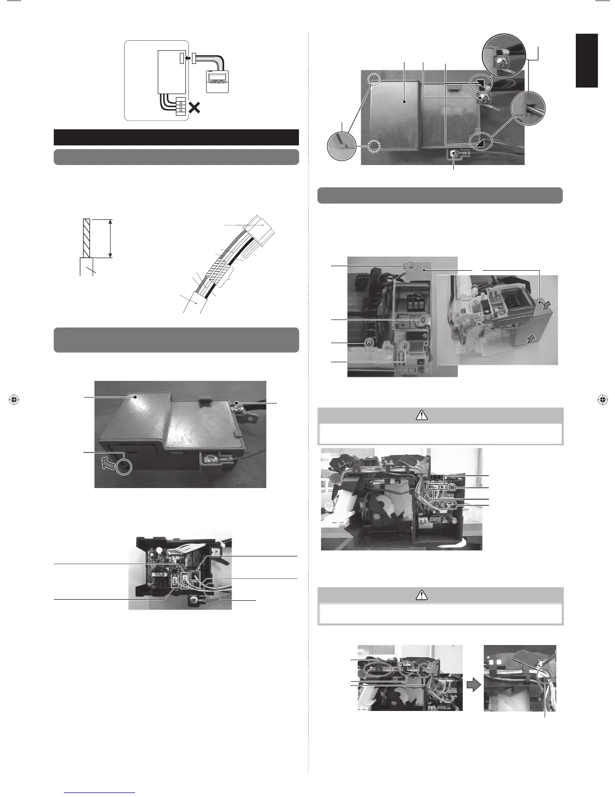
13.2.
Installing wired remote controller terminal /
external connect kit terminal (sold separately)
(1) Remove the screw on the control box as shown on the top right of the figure below.
(2) Release both bottom clasps at the sides in the direction of the arrow as circled in
the bottom left of the figure below. Pull and remove the cover.
(2)
(1)
Cover
(3) Connect the wired remote controller terminal / external connect kit terminal (sold
separately) to the specified terminal on the board as shown below. Please connect
to the connector with necessary function according to the actual usage.
(4) After connecting each terminal, thread the cables through the notch as circled on
the bottom right of the figure below.
(3) Control input (Operation/
Stop or Forced stop)
connector
: CNA01(White) *
(3) Wired remote controller
connector
: CNC01(White) *
* : Symbol indicating the location printed on the board
(3) Error Status output
connector
: CNB02(Black) *
(3) Operation status
output connector
: CNB01(White) *
(4)
(5) Install the control box cover as shown below.
(Align the cover with the upper and lower right corners as indicated by the triangular
symbols on the figure.
Insert the clasps on the cover into both sides at the bottom of the two dotted
circles.)
• When installing the control box cover, make sure that the cables are not caught as
shown in the detail view.
(6) Install one screw.
(7) Screw the earth wire of wired remote controller as shown
in the figure. (AUSTRALIA model only).
9333005072_IM.indb 79333005072_IM.indb 7 2013-9-24 11:45:072013-9-24 11:45:07
 Loading...