3. INSTALLATION
29
NMEA port setup, GPS WAAS setup
The NMEA port can function as an input port
or input/output port.
If you are using the GP-320B, turn on the
GPS WAAS feature.
1. Show the Installation menu and then
press ▼ to choose NMEA PORT.
2. Press ► to display the NMEA port options
window.
3. Press ▲ or ▼ to choose IN/OUT or IN/IN
as appropriate.
IN/OUT: Input and Output (default setting).
For GP-320B choose this setting.
IN/IN: Input only (Available with
connection of multiple navigators.)
4. If you selected IN/OUT at step 3, press ◄,
▼ to choose NMEA OUTPUT, and then
press ► to display the NMEA OUTPUT
options window.
5. Press ▲ or ▼ to choose OFF or ON.
Choose ON to output input data. Choose
OFF to not output data or if the GP-310B
or GP-320B is connected.
6. Press ◄ to close the window.
7. If the GP-320B is connected, press ▼ to
choose GPS WAAS. Otherwise, go to
step 10.
8. Press ► to open the window.
9. Press ▲ to choose message type.
Note: WAAS is currently in the
developmental stage. While in the
developmental stage choose message
type 02. Change to message type 00
when WAAS becomes fully operational.
10. Turn off the power.
3.5 Magnetron Heater Voltage
Note: This confirmation/adjustment should
only be performed by a qualified service
technician.
Magnetron heater voltage is formed at the
MD Board of the antenna unit and
preadjusted at the factory. Therefore, no
adjustment is required. However, verify
heater voltage as below.
WARNING
ELECTRICAL SHOCK HAZARD
Do not open the equipment.
DO NOT attempt the
procedure below unless
totally familiar with electrical
circuits.
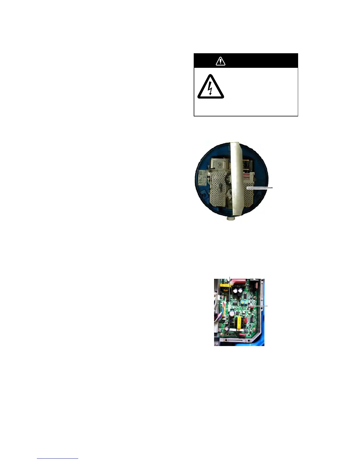
1. Open the antenna cover and remove the
shield plate.
MD board
(under
shield plate)
Antenna unit, inside view
2. Turn on the power. DO NOT transmit.
3. Connect a multimeter, set to 10 VDC
range, between #6 (+) and #4 (-) of test
point TP804.
TP804
VR801
MD board
4. Confirm that the multimeter shows 8.0 V
±0.1 V. If it does not, adjust potentiometer
VR801 on the MD Board.
5. Turn off the power.
6. Refasten the shield plate.
7. Close the antenna cover.
 Loading...