1. INSTALLATION AND WIRING
8
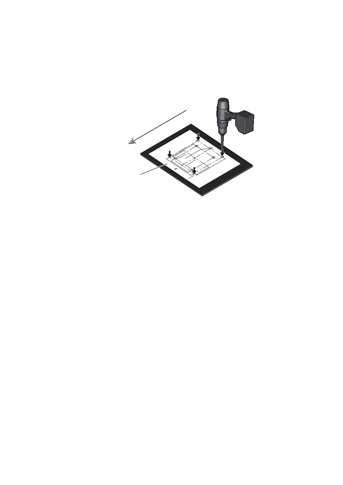
1.5 Mounting the Antenna Unit
The antenna unit can be mounted using the fixing holes (200 200 mm) of the anten-
na unit.
1. Set the supplied mounting template to the mounting location, then drill four fixing
holes in the mounting location.
Note: The holes must be parallel with the fore and aft line.
2. Apply adhesive to the thread of the stud bolts (M1270, 4 pcs).
Note: Apply adhesive to the part of the bolt threads that are inside the bolt hole
(see the figure at step 3).
3. Insert four stud bolts into the threaded holes in the antenna unit.
The stud bolts must make contact with the bottom of the threaded holes.
Note: Do NOT cover the vent hole at the bottom of the unit.
CAB
LE
E
NTRANCE AT SCANNER F
OR
DRS4A/6A/12A/25A
䝇䜻䝱䝘ഃ䜿䞊䝤䝹
ᑟධཱྀ䠄㻰㻾㻿
㻠㻭㻛㻢㻭㻛㻝㻞㻭㻛㻞㻡㻭䛾
䜏䠅
PP
'')
PP
''
)
sPP'
')
PP'')
sPP
'')
CENTE
R OF
ANTENNA RO
TATIO
N
䜰䞁䝔䝘ᅇ㌿୰ᚰ
PP
'
')
ྲྀ
✰
4-䃥
15
FIXING HO
LES
ྲྀ
✰䚷
㻔
⏝㻕
4-
䃥
15
(#:
4
p
laces)
FI
XING HOLES
( FOR
RETROF
ITTING)
Note: This temp
late m
a
y ha
ve
e
xpanded or sh
r
u
nk sli
ghtly.
Please c
onfirm
dimen
sions be
fore use.
ὀព㻦㻌㻌ᮏᆺ⣬䛿ಖᏑ≧ែ䛻䜘䜚ⱝᖸఙ⦰䛩䜛ሙྜ䛜
䛒䜚䜎䛩䚹
㻌㻌㻌㻌㻌㻌㻌㻌㻌⏝䛾㝿䛻䛿
ᑍἲ䜢☜ㄆ䛧䛶䛟䛰䛥䛔
䚹㻌
B
OW
⯪㤳᪉ྥ
DRSシリーズ レーダーセンサー(オープン型)
ᆺ⣬
DRS SERIES OPEN RADAR SENSOR
MOUNTING TEMPLATE
Bow
Mounting template