3. SETTINGS AND ADJUSTMENTS
3-5
5. Use the scrollwheel to set START and ANGLE, referring to the description and ex-
ample below. Spin the scrollwheel to set and push it to confirm.
A solid green line marks the dual radar display area.
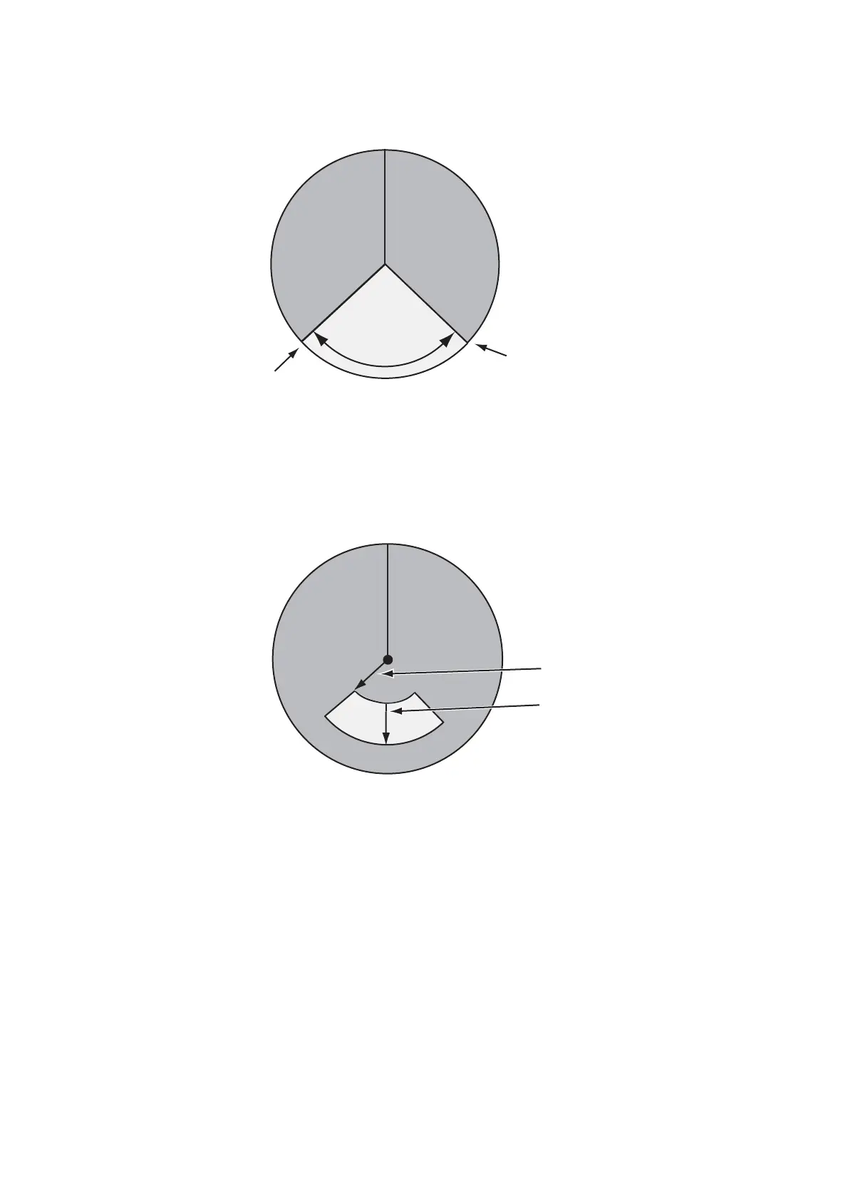
• START: Start point of the sector (in degrees, 000-359).
• ANGLE: Horizontal width of the sector (in degrees, 000-359).
6. Select [3 COMBINE RANGE] to set the vertical width of the sector.
7. Use the scrollwheel to set START and LENGTH, referring to the example below.
Spin the scrollwheel to set and push it to confirm.
• START: Distance from reference point to sector
• LENGTH: Vertical length of sector
3.5.3 How to select the external radar (image source) to use
The dual radar display works best with two FAR-3xx0 radars. Other makes or models
can be used, however performance may vary.
1. From the [RADAR INSTALLATION] menu, select [2 SCANNER]→[6 DUAL RA-
DAR SETTING].
2. Select [4 EXT RADAR].
3. Select required radar no. (Only the numbers of radar set on the [RADAR INSTAL-
LATION] menu are vaiid.)
Note 1: The dual radar will not function if a radar incompatible to the dual radar
function is selected.
START
(Example: 130°)
NGLE
(Example: 100°)
Width of sector
START
LENGTH
Example:
START: 01.00 nm
LENGTH: 02.00 nm
 Loading...