1. HOW TO INSTALL THE EQUIPMENT
5
1.2 Wiring
Connect a termination resistor at both ends of the backbone of CAN bus devices. PG-700 incor-
porates a termination resistor. Turn the switch on/off as applicable.
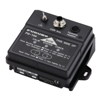
If using the optional Junction Box FI-5002
Connect the unit and the FI-5002 using cable M12-05BM+05BF-060 (supplied as installation ma-
terials). For connection at the FI-5002, cut the cable at the pre-connected connector, fabricate the
cable as shown below, then connect the cable to the MC connector at the FI-5002. Ground the
unit to the hull using the shortest IV-2sq cable possible.
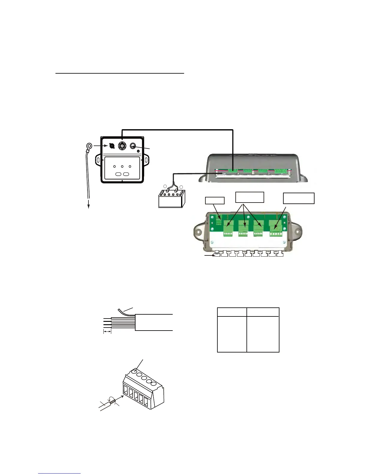
• How to fabricate cable M12-05BM+05BF-060 and connect MC connector
Red
Black
+
–
Connect to
CN2 - CN5.
Termination switch*1
Sensor
PG-700
12VDC
CN3 - CN5
DROP
JUNCTION BOX
FI-5002 (option)
Fix cable with
supplied cable ties.
FI-5002
Power cable (2m)
M12-05BM+05BF-060 (6m)
Side view
12VDC
Crimp-on lug
(inner dia. 3mm)
Ground wire*2
IV-2sq
To ground
Top view
*1: Turn the Termination switch
OFF to connect CN3 - CN5;
ON to connect CN2.
CN2
BACKBONE
MC connector
*2
*2: Prepared locally
Screw
Core
Twist
MC connector
6 mm
Sheath
Cable Fabrication
Drain wire
Wire Conn. Pt.
Drain 1
RED 2
BLK 3
WHT 4
BLU 5
How to insert cores:
1. Twist core.
2. Unfasten screw with flathead screwdriver.
3. Set core to hole.
4. Tighten screw.
5. Pull wire to confirm connection.
 Loading...