6
If necessary, use a file and sandpaper to refine the size of
the cutout.
7
After the stereo fits correctly in the cutout, ensure the
mounting holes on the stereo line up with the pilot holes on
the template.
8
If the mounting holes on the stereo do not line up, mark the
new pilot-hole locations.
9
Using an appropriately sized drill bit for the mounting surface
and screw type, drill the pilot holes.
10
Remove the template from the mounting surface.
11
Make the necessary wiring connections (Connection
Considerations,
page
2)
.
12
Select an option:
• If you are installing the stereo in a dry location, place the
included mounting gasket
Á
on the back of the stereo.
• If you are installing the stereo in a location that is exposed
to water, apply silicone-based marine sealant on the
mounting surface around the cutout.
NOTICE
Do not install the included mounting gasket if you applied
sealant to the mounting surface. Using sealant and the
mounting gasket may reduce water resistance.
13
Place the stereo into the cutout.
14
Secure the stereo to the mounting surface using the included
screws
Â
.
You should hand-tighten the screws when securing the
stereo to the mounting surface to avoid overtightening them.
15
Snap the screw covers in place
Ã
.
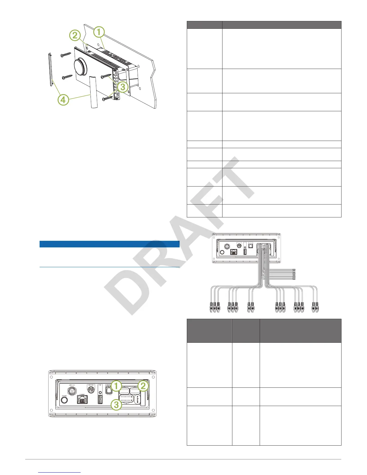
Connection Considerations
For the stereo to function correctly, you must connect it to
power, to speakers, and to input sources. You should carefully
plan the layout of the stereo, speakers, input sources, optional
NMEA 2000
network, and optional
FUSION PartyBus
™
devices
or network before making any connections.
Port Identification
Item Description
ANTENNA Connects the stereo to a typical AM/FM antenna.
If you are installing the stereo on a boat with a metal
hull, you must use a ground-dependent antenna. If you
are installing the stereo on a boat with a non-metal
hull, you must use a ground-independent antenna.
See the installation instructions provided with your
antenna for more information.
NMEA 2000 Connects the stereo to a
NMEA 2000 network (
NMEA
2000 System Wiring Diagram, page 4)
.
Connects to an NRX series remote control directly
(
Configuring an Optional Wired Remote,
page
4)
.
ETHERNET Connects the stereo to another FUSION PartyBus
stereo, zone stereo, or network (FUSION PartyBus
Networking,
page
4)
.
SIRIUS XM Connects the stereo to a
SiriusXM
®
Connect Tuner to
receive SiriusXM stations where available (not
included).
Connects to a FUSION DAB module to receive DAB
stations where available (not included).
USB Connects the stereo to a USB source.
DIGITAL
AUDIO IN
Connects the stereo to an optical digital audio source,
such as TV or DVD player.
FUSE Contains the 15 A fuse for the device.
À
Connects the stereo to the wiring harness for auxiliary
input 2, and for the line and subwoofer outputs for
zones 3 and 4.
Á
Connects the stereo to the wiring harness for auxiliary
input 1, and for the line and subwoofer outputs for
zones 1 and 2.
Â
Connects the stereo to the power and speaker wiring
harness.
Wiring Harness Wire and Connector Identification
Wire or RCA
Connector
Function
Bare Wire
Color or
RCA Label
Name
Notes
Ground (-) Black Connects to the negative terminal of
a 12 Vdc power source capable of
supplying 15 A. You should connect
this wire before connecting the
yellow wire. All accessories
connected to the stereo must share
a common ground location
(Connecting to Power,
page
3)
.
Power (+) Yellow Connects to the positive terminal of a
12 Vdc power source capable of
supplying 15 A.
Ignition Red Connects to a separately-switched,
12 Vdc connection, such as an
ignition bus, to turn the stereo on
and off. If you are not using a
switched 12 Vdc connection, you
must connect this to the same
source as the yellow (power) wire
2 Apollo RA770
Installation Instructions
 Loading...