Installation
22 Apollo SL30 Installation Manual
Rslvr{C}
Rslvr{D}
Rslvr{E}
24
7
26
25
1
2
3
6
5
4
Rslvr{H}
Rslvr{C}
Rslvr{D}
Rslvr{E}
Rslvr{F}
Rslvr{G}
Mid Cont MD200-306/307
+NAV Flag
-NAV Flag
+TO Flag
+FR Flag
CDI Left
CDI Right
+NAV Flag
-NAV Flag
+TO Flag
+FR Flag
+CDI Left
+CDI Right
10
29
12
11
14
13 12
11
10
9
8
7
Back Crse
ILS Enbl
15
33
BC Ann.18
To Auto-Pilot
High Sense
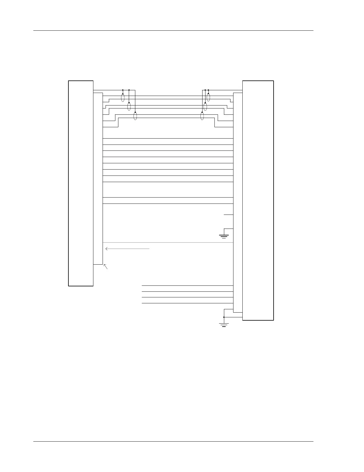
NOTES: 1. Use shieled cable for resolver signals
2. Connect cable shields to the mounting frame: pigtails < 1.25 inches
3. Connect shields chassis ground at both ends of each shielded cable
4. Reference the ACU installation manual if installing NAV/GPS source selector
Rslvr{F}
Rslvr{G}
Rslvr{H}
16
34
+GS Flag +Vert (GS) Flag
-Vert (GS) Flag
28
16
15
32-GS Flag
SL30
Nav Ann.24
17
30
31
14
+Up
+Down
GSI Up
GSI Down
13
GPS Ann.
* Ground for 14V lighting
**Appropriate Aircraft Bus
Ann. Pwr - 14V
28V Dimmer *
14V Dimmer
22
23
19
Ground21
Annunciator
Backlight Dimmer 14 V Systems
Backlight Dimmer 28 V Systems
Ann. Pwr - 28V20
Annunciator Power
+13.8 VDC **
+28 VDC **
N/C
37-Pin Connector
Figure 12 - SL30 NAV to Mid-Cont MD200-306/307