Instructions for Continued Airworthiness GTN 6XX/7XX - Eurocopter EC130 Series
Page 15 of 21 190-01007-K9 Rev. 1
panel, the circuit breaker panel is located in the cargo area and tail boom, as shown in Figure 6. In the EC
130 B4, the circuit breakers for the GTN 6XX are located on top of instrument panel support, or the right
hand side of the pedestal as shown in Figure 5.
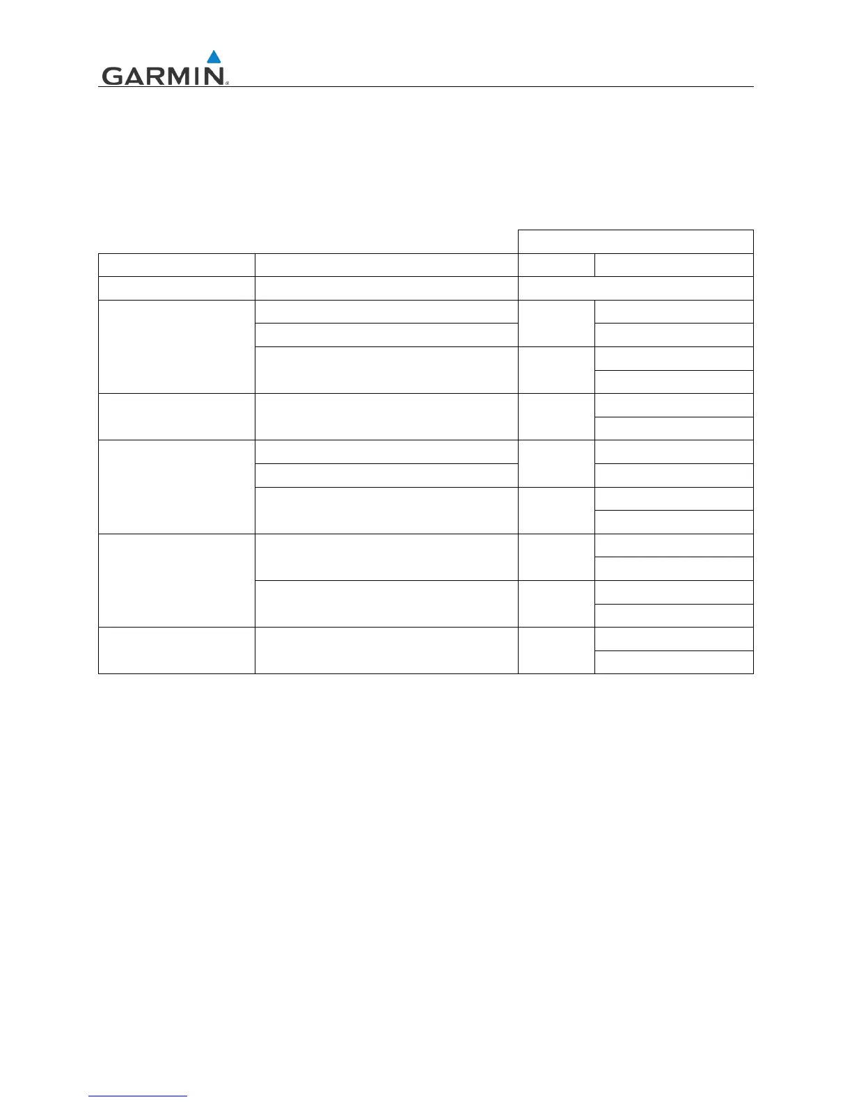
Equipment circuit breaker placards are labeled as follows:
Table 4. Circuit Breaker Labels
GTN INSTALLATION
LRU POWER INPUT SINGLE DUAL
GMA 35 Rotorcraft Power on Connector P3502 Audio
GTN 750
Rotorcraft Power on Connector P1001
GPS/NAV
GPS/NAV 1
Rotorcraft Power on Connector P1004 GPS/NAV 2
Rotorcraft Power on Connector P1003 COM
COM 1
COM 2
GTN 725 Rotorcraft Power on Connector P1001 GPS
GPS 1
GPS 2
GTN 650
Rotorcraft Power on Connector P1001
GPS/NAV
GPS/NAV 1
Rotorcraft Power on Connector P1004 GPS/NAV 2
Rotorcraft Power on Connector P1003 COM
COM 1
COM 2
GTN 635
Rotorcraft Power on Connector P1001 GPS
GPS 1
GPS 2
Rotorcraft Power on Connector P1003 COM
COM 1
COM 2
GTN 625 Rotorcraft Power on Connector P1001 GPS
GPS 1
GPS 2
1. Dual installation labeling applies to GTN LRUs only
The GTN and optional GMA 35 wiring harness power and switch connections are routed as shown in
Figure 4. Since the GTNs may be interfaced with preexisting GPS antennas, coaxial wire routing may
differ slightly from the depicted figure. Refer to the aircraft wire routing worksheets and equipment
location forms that were filled out during initial GTN/GMA 35 installation for additional details.
GTN/GMA 35 installation racks, back plates, and wiring harnesses may be accessed by removing the
GTN LRUs as specified in GTN 6XX/7XX PART 27 AML STC SYSTEM MAINTENANCE MANUAL
Section 5, Equipment Removal and Replacement.

 Loading...