Instructions for Continued Airworthiness GTN 6XX/7XX - Eurocopter EC130 Series
Page 21 of 21 190-01007-K9 Rev. 1
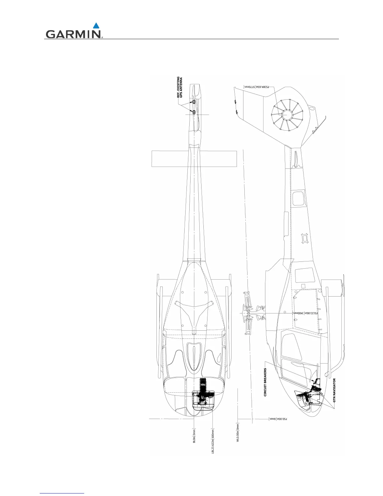
APPENDIX A EQUIPMENT LOCATIONS AND WIRE ROUTING
A.1 GTN 6XX/7XX STC Installation – Eurocopter EC 130 Series
The following diagram must be
completed to depict the location of
all LRUs and antenna(s) along with
the wire routing for the GTN
6XX/7XX and GMA 35 throughout
the aircraft structure for the
Eurocopter EC 130 rotorcraft. All
harnesses fabricated as part of this
STC should be included in this
diagram.

 Loading...