11
WARNING: To avoid possible electric
shock, be sure electricity is turned
off at the main fuse box before wiring.
NOTE: Fan must be installed at a
maximum distance of 6.1 m (20
ft.) from the transmitting unit for
proper signal transmission between
the transmitting unit and fan’s
receiving unit.
CAUTION: Do not use wall switch
with dimmer function.
WARNING: Check to see that all
connections are tight, including
ground wire, and that no bare wire
is visible at the wire nuts, except for
the ground wire.
WARNING: Electrical diagrams are
for reference only. Optional use of
any light kit shall be UL listed and
marked suitable for use with this fan.
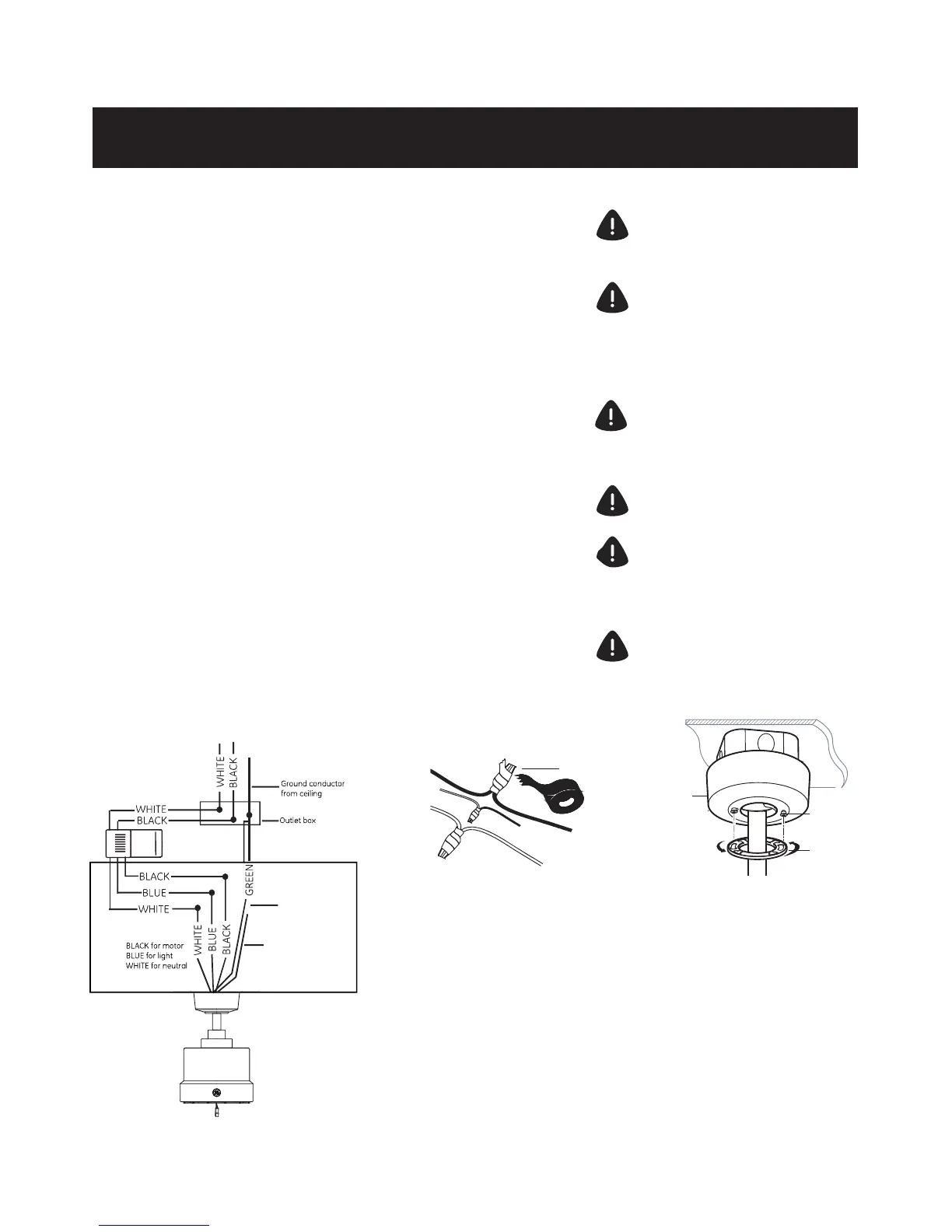
MAKING THE ELECTRICAL CONNECTIONS
Supply Circuit
Motor to receiver electrical connections: Connect the black
wire from the fan to black wire marked “TO MOTOR L” from
the receiver. Connect the white wire from the fan to the
white wire marked “TO MOTOR N” from the receiver. Connect
the blue wire from the fan to the blue wire marked “For Light”
from the receiver. Secure the wire connections with the
plastic wire nuts (H) and electrical tape.
Receiver to house supply wires electrical connections:
Connect the black (hot) wire from the ceiling to the black
wire marked “AC in L” from the receiver. Connect the white
(neutral) wire from the ceiling to the white wire marked “AC
in N” from the receiver. Secure the wire connections with the
plastic wire nuts (H) and electrical tape.
If your outlet box has a ground wire (green or bare copper),
connect it to the ground wire from mounting bracket and
the ground wire from downrod assembly, secure the wire
connection with a plastic wire nut (H); otherwise connect the
ground wire from mounting bracket to the ground wire from
downrod assembly, secure the wire connection with plastic
wire nut (H) and electrical tape.
After connecting the wires, spread them
apart so the green and white wires are on
one side of the outlet box and the black
and blue wires are on the other side.
Carefully tuck the wire connections up into
the outlet box.
Lift the canopy (R) up to the ceiling and
install the canopy (R) to the mounting
bracket (Q) by using the canopy mounting
screws (AA). Attach the canopy bottom
cover (S) to the canopy mounting screw
(AA) heads by inserting the screw heads
into the key slots in the canopy bottom
cover (S) and rotating the canopy bottom
cover (S) clockwise.
NOTE: Adjust the canopy mounting screws
(AA) as necessary until the canopy (R) and
canopy bottom cover (S) are snug.
Fan installation
H
R
AA
S
NOTE : For best remote control
reception, make sure the brown antenna
wire is placed away from the electrial
wires (blue, white and black colors).
Ground wire
from downrod
assembly
Ground wire
from mounting
bracket
 Loading...