6 – 9
ATEX Instruction Manual GEA19513 – 03/2012
4700E and 4800E Series Electropneumatic Positioners
5. ELECTRICAL CONNECTIONS and CONDUIT ENTRY
Comply with current national and local regulations for electrical installation work.
Comply with national and local explosive atmosphere regulations.
Before carrying out any work on the device, power off the instrument or make sure that the local
conditions in the potentially explosive atmosphere permit the safe opening of the cover.
Before switching on or after doing any work on the device, always tighten the cover (C) with a seal (J) in
good condition and put back the safety screw (V).
The Model 4000 I/P Converter must be installed and put into service in conformance with EN/IEC 60079-14,
EN/IEC 61241-14 and / or national and local regulations applicable for explosive atmospheres.
5.1. Current signal
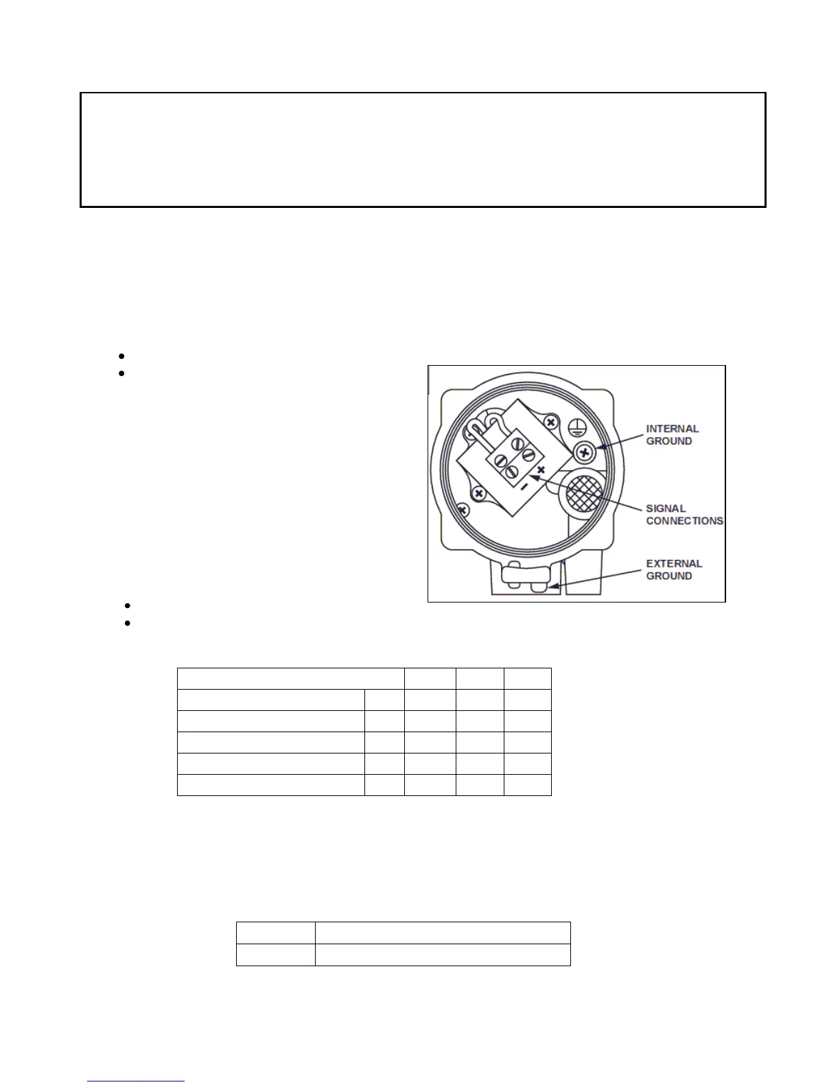
The Model 4000 I/P Converter is self-powered 4-20mA current receiver. Connect the wires to the instrument's
terminals, taking care of complying with polarities + and - .
Make the earth connections with the internal and external ground terminals.
Input signal: 4-20 mA,
Input impedance: 170 ohms.
5.2. Maximum Power
0.8 W for Flameproof atmosphere
1.1W or 0.33W for Intrinsic Safety atmosphere
5.3. Intrinsic Safety entity parameters
5.4. Conduit entry in flameproof application
The connections can be done with different variations taking into account approved manufacturer and requested
approvals:
A cable entry of a certified type Ex d IIC / Ex tD A21 or Ex t IIIC Db can be mounted directly on the single ½"
NPT (ANSI/ASME B1.20.1) housing conduit connection or M20 (ISO965-1 & ISO965-3).
For identification machining thread, check the part number sticked on the Model 4000 I/P Converter body:

 Loading...


