330400 and 330425 Accelerometer Operation Manual
A®
SIGNAL
Bo
0
-1
Co
\1
0
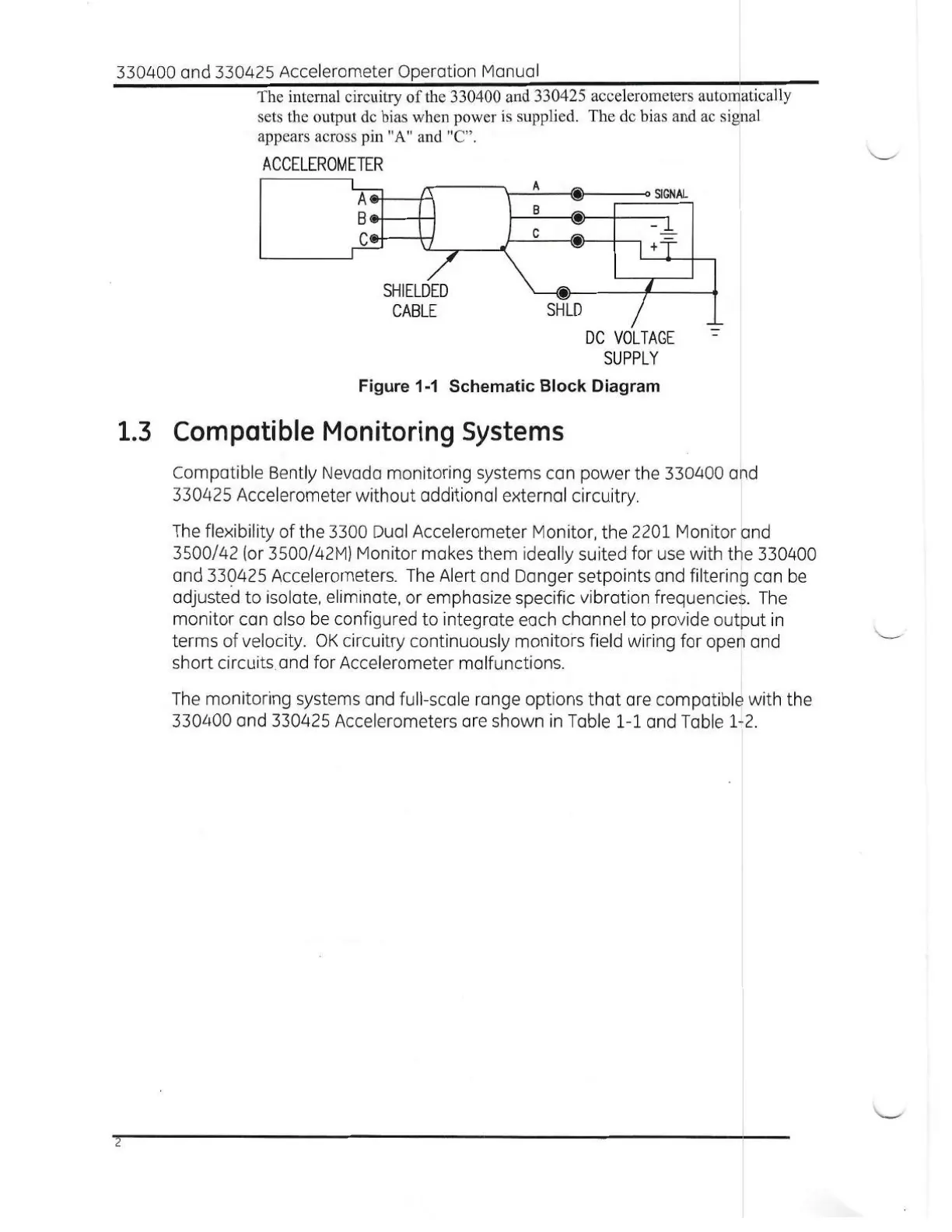
The internal circuitry of the 330400 and 330425 accelerometers automatically
sets the output dc bias when power is supplied. The dc bias and ac signal
appears across pin "A" and "C".
ACCELEROMETER
SHLD
0
DC VOLTAGE
SUPPLY
Figure 1-1 Schematic Block Diagram
SHIELDED
CABLE
1.3 Compatible Monitoring Systems
Compatible Bently Nevada monitoring systems can power the 330400 and
330425 Accelerometer without additional external circuitry.
The flexibility of the 3300 Dual Accelerometer Monitor, the 2201 Monitor and
3500/42 (or 3500/42M) Monitor makes them ideally suited for use with the 330400
and 330425 Accelerometers. The Alert and Danger setpoints and filtering can be
adjusted to isolate, eliminate, or emphasize specific vibration frequencies. The
monitor can also be configured to integrate each channel to provide output in
terms of velocity. OK circuitry continuously monitors field wiring for open and
short circuits and for Accelerometer malfunctions.
The monitoring systems and full-scale range options that are compatible with the
330400 and 330425 Accelerometers are shown in Table 1-1 and Table 1-2.
2

 Loading...