15
5.2 Fuse Replacement Steps
1. All upstream devices that could energize the fuse should be opened, padlocked, and tagged so that
inadvertent closure cannot create a hazard.
2. The BreakMaster switch is opened by rotating the handle downward.
3. Before opening the door look through the viewing window to visually verify that all blades are disengaged from
their stationary contacts. Use a flashlight if necessary.
4. After opening the door, an appropriate medium voltage-sensing device, such as a TIC tracer rated up to 15kV,
should be used to determine if voltage is present. An example would be TIC brand, TIF320HV.
5. If no voltage is present, a suitable grounding device should be attached to the fuse terminals to discharge any
static charge and assure that the fuse terminals remain at ground potential.
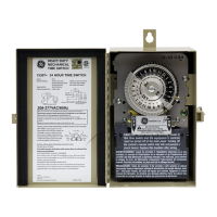
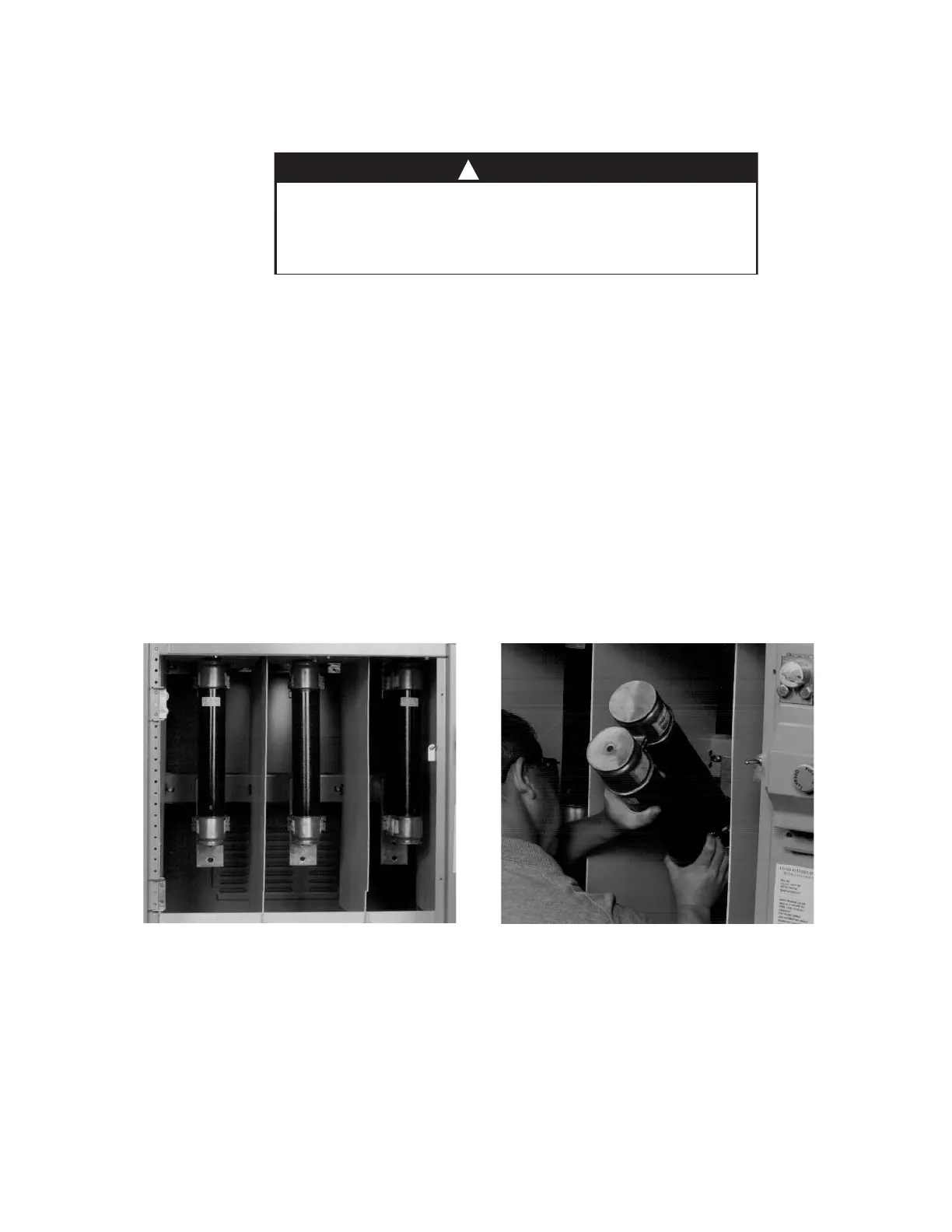
6. Remove fuse by pulling fuse forward until it is clear of the fuse clips. Install new fuse by inserting it into the fuse
clips. Make sure the clips fully contact the fuse ferrules. See Figures 16 and 17.
DANGER
W
hen accessing fuses, failure to assure that the fuses are deenergized may result
in equipment damage, bodily injury or death.
Make sure that all power sources are deenergized before attempting to
a
ccess the fuses.
!
Figure 16
Installed Fuses
Figure 17
BreakMaster Load Interrupter Switch
 Loading...