17
BreakMaster Load Interrupter Switch
O
peration (motor operated switch)
This drive system consists of:
1. Heavy Duty Universal Gear Motor (M)
2. Full-Wave Bridge Rectifier (RECT)
3. Double-throw Contactor 3-Pole or 4-Pole (89XY)
4
. Industrial Solenoid (SOL)
5. Clutch and Spring Mechanism Coupled to the Drive Motor (CL & SP)
6. Load Interrupter Switch Auxiliary Cam Switch
Chain Driven
Normally Open (89/OP)
Normally Closed (89/CL)
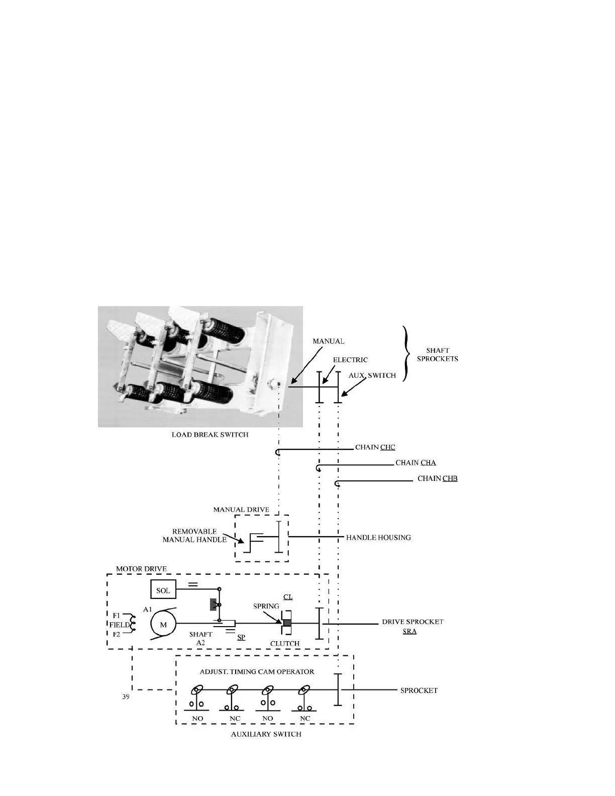
See Kinematic Diagram (Figure 18). When the main interrupter (89) is signaled to operate (close), the 89X coil
(Figure 19) is energized, closing all of its contacts and mechanically blocking 89Y from being energized. Solenoid
(SOL) is then energized.
Figure 18
Motor Drive System Kinematic Diagram
 Loading...