11 12
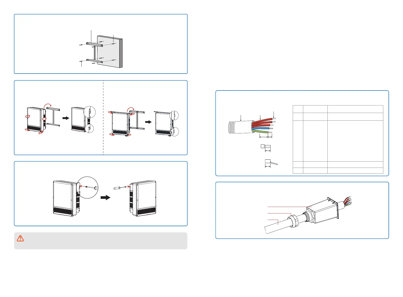
Backboard Installation
Step 2: with the expansion of the accessory package the screw back on the wall.
Expansion Screw
Tapping screw
Back hangs Taiwan
need card in the card
buckle
Back hangs Taiwan
need card in the card
buckle
Step 4: the accessory bag on both sides of the security screw locking to inverter, make its fixed
on the flip chart.
Step 3: two people holding will on both sides
of the inverter in the back flip chart.
If equipped with a hand, please install the
handle to the inverter, then as shown in the
figure below Inverter to hang in the back flip
chart.
4.3 Electrical Installation
4.3.1 AC side lines connection
1. Measure the voltage and frequency of the grid access point, determine the grid specifications
conform to the inverter.
2. Suggest increase the ac circuit breaker or fuse, the specification of ac output more than 1.25
times the rated current.
3. The inverter of PE line (ground) must be reliable grounding, ensure that the impedance
between the zero line and ground wire is less than 10 ohms.
4. Disconnect the inverter and grid access point of the circuit breaker or fuse.
5. It is recommended to use copper wire, if you need to use aluminum wire, please consult the
inverter manufacturers.
6. Follow these steps to connect the utility and inverter.
Step 1: Choose the appropriate communication cable and wire stripping out, specifications,
please refer to the table below.
GEP12~20-L-10/GEP25~36-10:
10 ~ 25 was 16 was recommended to use
copper wire
GEP30~35-L-10/GEP50~60-10:
35 ~ 50 was 50 was recommended to use
copper wire, aluminum wire suggested was 70
As cable diameter and distribution terminals,
or cable for aluminium wire, please contact
our service personnel
DC
D
D
A B
More soft copper wire
terminal
Cold pressed terminals
Grade Description Value
A
B
Wire diameter
Cross-sectional
area of the wire
C Wire length About 40 mm
D Bare wire length About 20 mm
GEP12~20-L-10/GEP25~36-10: 22~30mm
GEP30~35-L-10/GEP50~60-10: 30~40mm
Step 2: Remove the ac wiring cover from the accessory bag and wriggled nut, and then
communication cable through the parts as shown.
Communication terminal cover
nut
Communication cable
Two mounting holes in the middle of the wall-mounted bracket are only used for single
column installation, other environments may not be used.
 Loading...


