09 10
4.2 Equipment Installation
4.2.1 Select The Installation Location
1. Take the bearing capacity of the wall into account. The wall (such as concrete walls and metal
structures) should be strong enough to hold the weight of the inverter over a long period of
time.
2. Install the unit where it is accessible to service or do the electrical connection.
3. Do not install the unit on the wall of flammable material.
4. Make sure the installation location is well ventilated.
5. Inverters should not be installed near flammable or explosive items. Any strong electro-magnet-
ic equipment should be kept away from installation site.
6. Install the unit at eye level to for convenient operation and maintenance.
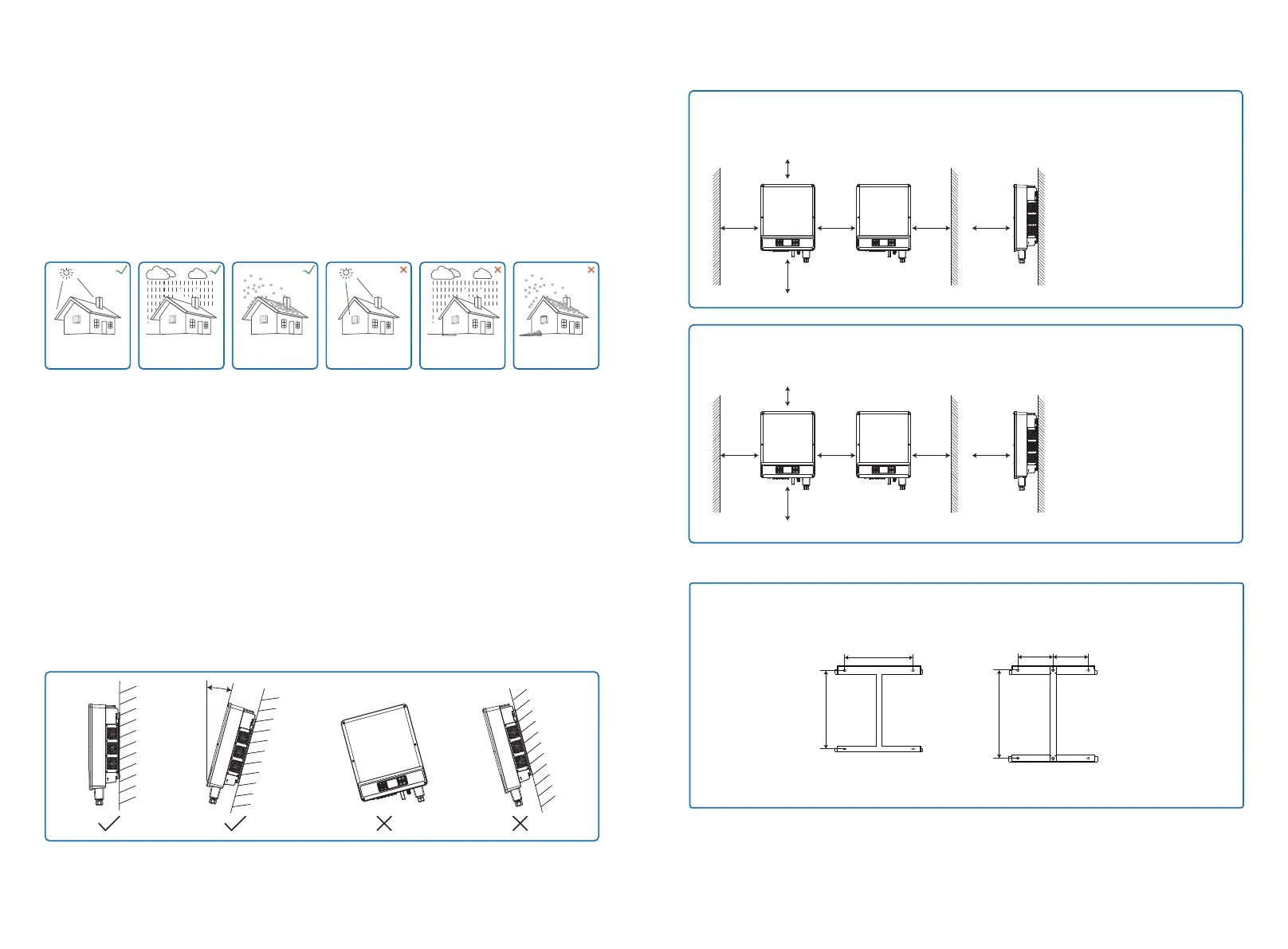
7. Install the unit vertically or tilted backwards of no more than 15 degrees, and wiring area should
should be facing downwards. Horizontal installation requires more than 250mm off the ground.
Max
15°
To ensure heat dissipation and convenient disassembly, the minimum clearance around the
inverter should not be less than the following values.
The Upward part
The downward part
The front part
Both sides
Interval
------------ 200mm
-------- 500mm
---------------- 500mm
------------------- 600mm
----------------------- 1200mm
500mm
1200mm600mm 600mm 500mm
200mm
The Upward part
The downward part
The front part
Both sides
Interval
------------ 500mm
-------- 500mm
---------------- 500mm
-------------------- 1000mm
----------------------- 1200mm
500mm
1200mm1000mm 1000mm 500mm
500mm
4 Installation
4.1 Mounting Instructions
1. In order to achieve optimal performance, the ambient temperature should be lower than 45℃.
2. For easy maintenance, we suggest to install the inverter at eye level.
3. Inverters should not be installed near flammable and explosive items. Strong electro-magnetic
charges should be kept away from installation site.
4. Product label and warning symbols should be placed at a location that is easy to read by the
users.
5. Make sure to install the inverter at a place where it is protected from direct sunlight, rain and
snow.
Accmulated snow
Keep away
from sunlight Keep dry
Keep it clear
of snow Sun Rain
4.2.2 Mounting Procedure
GEP12~20-L-10
GEP25~36-10
GEP30~35-L-10
GEP50~60-10
Step 1: Use back hangs Taiwan locates, hole on the wall, 10 mm in diameter, depth of 80 mm,
the size of the hole as shown in the figure below.
360mm
200mm 200mm
412mm
500mm
GEP12~20-L-10
GEP25~36-10
GEP30~35-L-10
GEP50~60-10
 Loading...


