Operating Instructions
Safety Instructions
Installation Instructions
Troubleshooting TipsCustomer Service
Installation of the downdraft system.
Read these instructions completely and carefully.
30″ Induction Cooktops with Downdraft Unit JVB37
36″ Induction Cooktops with Downdraft Unit JVB67
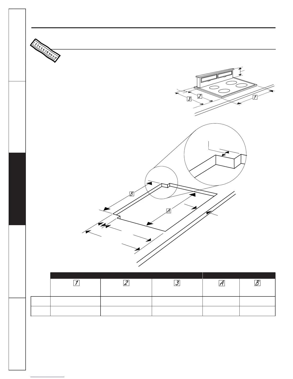
NOTE: Before you begin: Measure and mark 22
7
⁄
8
″ (Dimension 3) to ensure that adequate flat
countertop surface is available.
■ Identify the cutout illustration for the cooktop
model you are installing with this downdraft vent.
■–Draw lines on the countertop to follow as a
cutting guide.
■–Make sure sides of the opening are parallel and
rear and front cuts are exactly perpendicular to sides.
Planning Installation 30” Electric & Gas Cooktops with Downdraft Vents Preparing Cutout
Cooktop Surface Cooktop Surface Surface Depth Cooktop Cutout Vent Cutout
Model No.
Overall Width Overall Depth with Downdraft Width Width
JP392 30″ 20-3/4″ 22-7/8″ 29-1/8″ 28-1/2″
JP393
JP692 35-1/2″ 20-3/4″ 22-7/8″ 34-5/8″ 34″
JP693
12
5/16″
2″ Minimum
setback to front
edge of countertop
2
1
⁄
4
″
19
15
⁄
16
″
22
3
⁄
16
″
2
1
⁄
8
″
8
1
⁄
2
″
 Loading...