16
Installation of the downdraft system.
Read these instructions completely and carefully.
Step 3 is for 36″ wide models only. Skip this step if installing a 30″ model.
Operating Instructions
Safety Instructions
Installation Instructions
Troubleshooting TipsCustomer Service
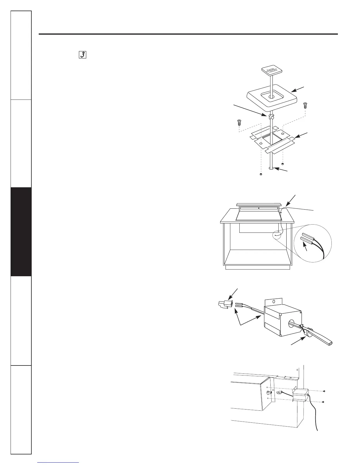
Install Raise/Lower Switch
Determine the location for the RAISE/LOWER
switch. The wiring lead is 72″ long.
■ Drill a 1/8″ hole into the desired location.
■ –If switch is mounted into a tile surface, drill
the hole between tiles. Use locally approved
caulking to cover any gaps.
■ Thread the wire lead through the top of
the countertop.
■ Thread the wire lead into the end of the
wire box.
■ Push wire metal leads into the white
connector plug.
■ Plug the connector into the control box.
■ Place plastic strain relief over wire, the
wire should be flat and fit into the area.
Do not pinch or twist the wire. Snap the
strain relief closed.
■ Push the strain relief into the hole on the wire
box. It will snap into position.
■ Secure wire box to vent with screws provided.
■ Center the mounting bracket over the hole and
mark pilot holes. Remove and drill pilot holes.
■ Mount the metal switch bracket with screws
(not provided, choose screws for your type of
countertop or use locally approved adhesive).
■ Tie a knot in the lead as close to the switch as
possible. This will prevent the lead from being
pulled away from the switch.
■ Peel film from the back of the switch trim to
expose the adhesive.
■ Press trim onto the mounting bracket to set
the adhesive.
IMPORTANT:
Do not connect wire leads to white
connector until you have threaded the lead
through the countertop hole and through the
end of the wire box.
■ Push wire metal leads into the white
connector plug.
■ Place plastic strain relief over wire, the
wire should be flat and fit into the area.
Do not pinch or twist the wire. Snap the
strain relief closed.
■ Push the strain relief into the hole on the wire
box. It will snap into position.
■ Secure wire box to vent with screws provided.
Trim
Knot
Mounting
bracket
Thread electrical
leads through hole
2 Pin connector
Hole
Leads
Strain relief
Pull 2″ length
out of box
 Loading...