Home
GE
Circuit breakers
MicroVersaTrip Plus
GE MicroVersaTrip Plus User Manual
4
of 1
of 1 rating
52 pages
Give review
Manual
Specs
To Next Page
To Next Page
Loading...
g
MicroVersaTrip Plus™ and
MicroVersaTrip PM™ Trip Units
for
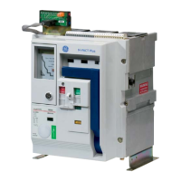
Type AKR Low-Voltage Power Circuit Breakers
Power Break
®
Insulated-Case Circuit Breakers
Power Break
®
II Insulated-Case Circuit Breakers
R-Frame Molded-Case Circuit Breakers
Low-Voltage Power Circuit Breaker Conversion Kits
User’s Guide
GEH–6273E
2
Table of Contents
Default Chapter
4
Table of Contents
4
Chapter 1. Introduction
11
1-1 Read this First
11
1-2 Product Structure
11
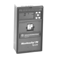
Front View of Microversatrip PM Trip Unit (Series RMS9C)
11
Front View of Microversatrip PM Trip Unit (Series RMS9D)
11
Rear View of Microversatrip PM Trip Unit (Series RMS9C)
12
Rear View of Microversatrip PM Trip Unit (Series RMS9D)
12
1-3 Trip Unit Functions
13
1-4 Trip Unit Catalog Numbers
13
Breaker Type Referred to by First Character of Trip Unit Catalog Number
13
Breaker Frame Size Maximum CT Referred to by Second Character of Trip Unit Catalog Number
14
Installed Breaker CT Size Referred to by Third and Fourth Characters of Trip Unit Catalog Number
14
Trip Unit Catalog Number Suffixes for Optional Functions
14
Microversatrip PM Trip Unit Suffixes for Communication, Metering, and Relaying
14
1-5 Rating Plugs
15
Rating Plug Catalog Numbers
15
1-6 Equipment Interfaces
16
Microversatrip Plus Trip Units
16
Neutral Current Sensors
16
Microversatrip PM Trip Units
16
POWER LEADER Communication Network
16
Voltage Inputs
16
Power Requirements
17
1-7 Trip Unit Information
17
Trip Unit Label Information
17
Function Keys
17
Labels on Front of Trip Unit
17
Battery Function
18
Function Key Placement on Face of Trip Unit
18
Liquid Crystal Display
19
Microversatrip Plus and Microversatrip PM Accuracies
19
Liquid Crystal Display Segments
19
Protective Relay and Metering Accuracies and Resolutions
19
Trip-Time Curves for Breaker Types Covered in this Guide
19
Chapter 2. Setup Mode
20
2-1 Overview
20
2-2 Operating Modes
20
2-3 Setup Mode Operation
20
Abbreviations Used in Setup Procedure Descriptions
20
Operation of FUNCTION Key, Showing Progression Among Trip Unit Operating Modes
21
Actions of Function Keys in Trip Unit Operating Modes
21
Trip Unit Setup Mode Programming Function Flow
22
Long-Time Pickup
26
Long-Time Delay
26
Short-Time Pickup
26
Trip Unit Display for Long-Time Pickup
26
Time-Current Curve Illustrating Long-Time Pickup
26
Trip Unit Display for Long-Time Delay
26
Time-Current Curve Illustrating Long-Time Delay
26
Lower-Limit Delays for Long-Time Delay Bands
26
Short-Time Delay
27
Trip Unit Display for Short-Time Pickup Coupled with Long-Time Pickup
27
Time-Current Curve Illustrating Short-Time Pickup
27
Trip Unit Display for Short-Time Delay
27
I 2 T out
27
Time-Current Curve for Short-Time Delay with
27
I 2 T in
27
Instantaneous Pickup
28
High-Range Instantaneous Overcurrent Protection
28
Ground-Fault Pickup
28
Trip Unit Display for Instantaneous Pickup
28
Instantaneous Overcurrent Protection Set Point
28
Trip Unit Display for Ground-Fault Pickup
28
Instantaneous Pickup Settings for Various Frame Sizes with and Without the Short-Time Function
28
Ground-Fault Pickup Settings, as a Function of Sensor Rating
28
Ground-Fault Delay
29
Voltage-Unbalance Relay Pickup
29
Time-Current Curve for Ground-Fault Pickup
29
Trip Unit Display for Ground-Fault Delay, Showing
29
I 2 T out
29
Time-Current Curve for Ground-Fault Delay with I 2 T out
29
Time-Current Curve for Ground-Fault Delay with
29
I 2 T in
29
Lower-Limit Delays for Ground-Fault Delay Bands
29
Voltage-Unbalance Relay Delay
30
Current-Unbalance Relay Pickup
30
Current-Unbalance Relay Delay
30
Undervoltage Relay Pickup
30
Undervoltage Relay Zero-Volt Trip Enable
30
Trip Unit Display for Voltage-Unbalance Relay Pickup
30
Trip Unit Display for Voltage-Unbalance Relay Delay
30
Trip Unit Display for Current-Unbalance Relay Pickup
30
Trip Unit Display for Current-Unbalance Relay Delay
30
Trip Unit Display for Undervoltage Relay Pickup
30
Undervoltage Relay Delay
31
Overvoltage Relay Pickup
31
Overvoltage Relay Delay
31
Power-Reversal Relay Pickup
31
Trip Unit Display for Undervoltage Relay Zero-Volt Trip Enabled
31
Trip Unit Display for Undervoltage Relay Delay
31
Trip Unit Display for Overvoltage Relay Pickup
31
Trip Unit Display for Overvoltage Relay Delay
31
Trip Unit Display for Power-Reversal Relay Pickup
31
Trip Unit Display for Power Direction Setup, Showing Line to Load
31
Trip Unit Display for Power-Reversal Relay Delay
32
Trip Unit Display for Rating Plug Current Set Point
32
Trip Unit Display for Potential Transformer Primary Voltage Set Point
32
Trip Unit Rating Plug Options
32
Trip Unit Display for Potential Transformer Connection Choice
33
Trip Unit Display for Power Demand Interval
33
Trip Unit Display for Setting Communication Address
33
Logic Diagram for Accessory Configurations
33
Power Demand Intervals
33
Accessory Configuration Switch on Rear of Trip Unit, Showing Factory Settings
34
Setting the Accessory Configuration Switches
34
Accessory Configuration Switch Settings, Including Factory Defaults
34
Trip Unit Metering Mode Function Flow
35
Overview
35
Trip Unit Display for Current Metering
37
Trip Unit Display for Line-To-Neutral Voltages
37
Trip Unit Display for Line-To-Line Voltages
37
Trip Unit Display for Aggregate Energy
37
Trip Unit Display for Aggregate Real Power
37
Current
37
Trip Unit Display for Aggregate Apparent Power
38
Trip Unit Display for Power Demand
38
Trip Unit Display for Frequency
38
Trip Unit Display for Normal Status
39
Chapter 3 . Metering Mode
39
Chapter 4 . Status Mode
39
Overview
39
Trip Unit Status Display for Long-Time Overcurrent Pickup
40
Typical Fault Display Following a Breaker Trip
40
Trip Unit Status Display for Long-Time Overcurrent Trip
40
Trip Unit Status Display for Short-Time Overcurrent Trip
40
Trip Unit Status Display for Instantaneous Overcurrent Trip
40
Trip Target and Fault Displays
40
Trip Unit Status Display for Ground-Fault Trip
41
Trip Unit Status Display for Protective-Relay Trip
41
Trip Unit Status Display for Undervoltage Release Trip
41
Trip Unit Display Targets for Protective Relays
41
Trip Unit Status Display for Long-Time Overcurrent Trip Counter
42
Clearing the Trip Operations Counters
42
Chapter 5 . Maintenance and Trouble-Shooting
43
Trip Unit Removal and Replacement
43
Removing the Interchangeable Rating Plug
44
Rating Plug Removal and Replacement
44
Trip Unit Battery Suppliers
49
Other manuals for GE MicroVersaTrip Plus
User Manual
36 pages
Manual
2 pages
Installation Instructions
28 pages
4
Based on 1 rating
Ask a question
Give review
Questions and Answers:
Need help?
Do you have a question about the GE MicroVersaTrip Plus and is the answer not in the manual?
Ask a question
GE MicroVersaTrip Plus Specifications
General
Brand
GE
Model
MicroVersaTrip Plus
Category
Circuit breakers
Language
English
Related product manuals
GE MicroVersaTrip PM
52 pages
GE MicroVersaTrip Plus Series
52 pages
GE MicroVersaTripPlus AK-50
26 pages
GE M-PACT
35 pages
GE ML-14-0
36 pages
GE M-Pact Plus
76 pages
GE Magne-Blast AM-13.8-1000-3H
50 pages
GE AKR
63 pages
GE FD 63
4 pages
GE AK-15
28 pages
GE AM-4.16-250-9
32 pages
GE Power Break II
118 pages