NX-4V2 Control 41
XVIII. APPENDIX 3
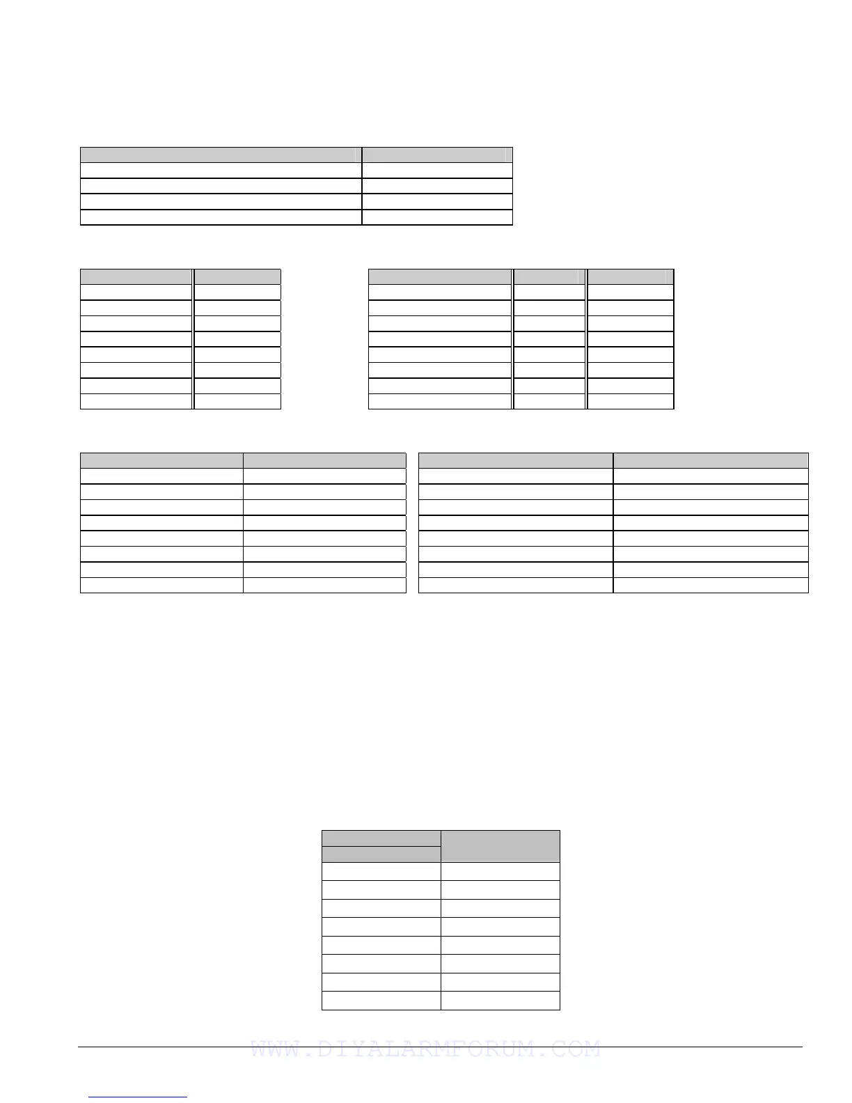
EXPANDER NUMBERS FOR REPORTING EXPANDER TROUBLE
The tables below list the device numbers that will be reported for trouble conditions.
Device Device # reported
NX-4V2 Control Panel 0 See page 39 for possible report codes.
NX-534E Two Way Listen-In 64
NX-540E “Operator” 40
NX-591E Cellemetry Interface 76
KEYPADS REMOTE POWER SUPPLY (NX-320E)
KEYPAD DEVICE # Switch Setting Address
1 192 All switches off 84
2 200 Switch 1 on 85
3 208 Switch 2 on 86
4 216 Switch 1 & 2 on 87
5 224 Switch 3 on 88
6 232 Switch 1 & 3 on 89
7 240 Switch 2 & 3 on 90
8 248 Switches 1, 2, & 3 on 91
WIRELESS RECEIVER (NX-448E) OUTPUT MODULE (NX-508E)
Switch Setting Expander # reported Switch Setting Address
All switches off 35 Switch 1 & 2 on 24
Switch 1 on 36 Switch 3 on 25
Switch 2 on 37 Switch 1 & 3 on 26
Switches 1 & 2 on 38 Switch 2 & 3 on 27
Switch 3 on 39 Switch 1,2,&3 on 28
Switches 1 & 3 on 32 All switches off 29
Switches 2 & 3 on 33 Switch 1 on 30
Switch 1, 2 & 3 on 34 Switch 2 on 31
XIX. APPENDIX 4
USER ID OR ZONE ID HEX DIGIT FOR 4+2 FORMATS
The following appendix applies only to slow formats (locations 56- 83 lower digit). The digit programmed in the locations will be
sent as the upper HEX digit in place of the alarm event code. The zone ID or user ID will always be reported as the lower HEX digit (1-
F) as shown in the chart below. For example, if the zone ID or user ID is 6, the 4+2 lower digit will be “6”. Use the chart shown below
for convenience.
If Segments 2-8 are left as “0” (unprogrammed), they will follow the Segment 1 selection. If Segment 1 is left as “0” and the
feature is enabled in Location 23, the NX-4V2 will report “A”.
ZONE
USER
HEX
1 1
2 2
3 3
4 4
5 5
6 6
7 7
8 8
WWW.DIYALARMFORUM.COM

 Loading...