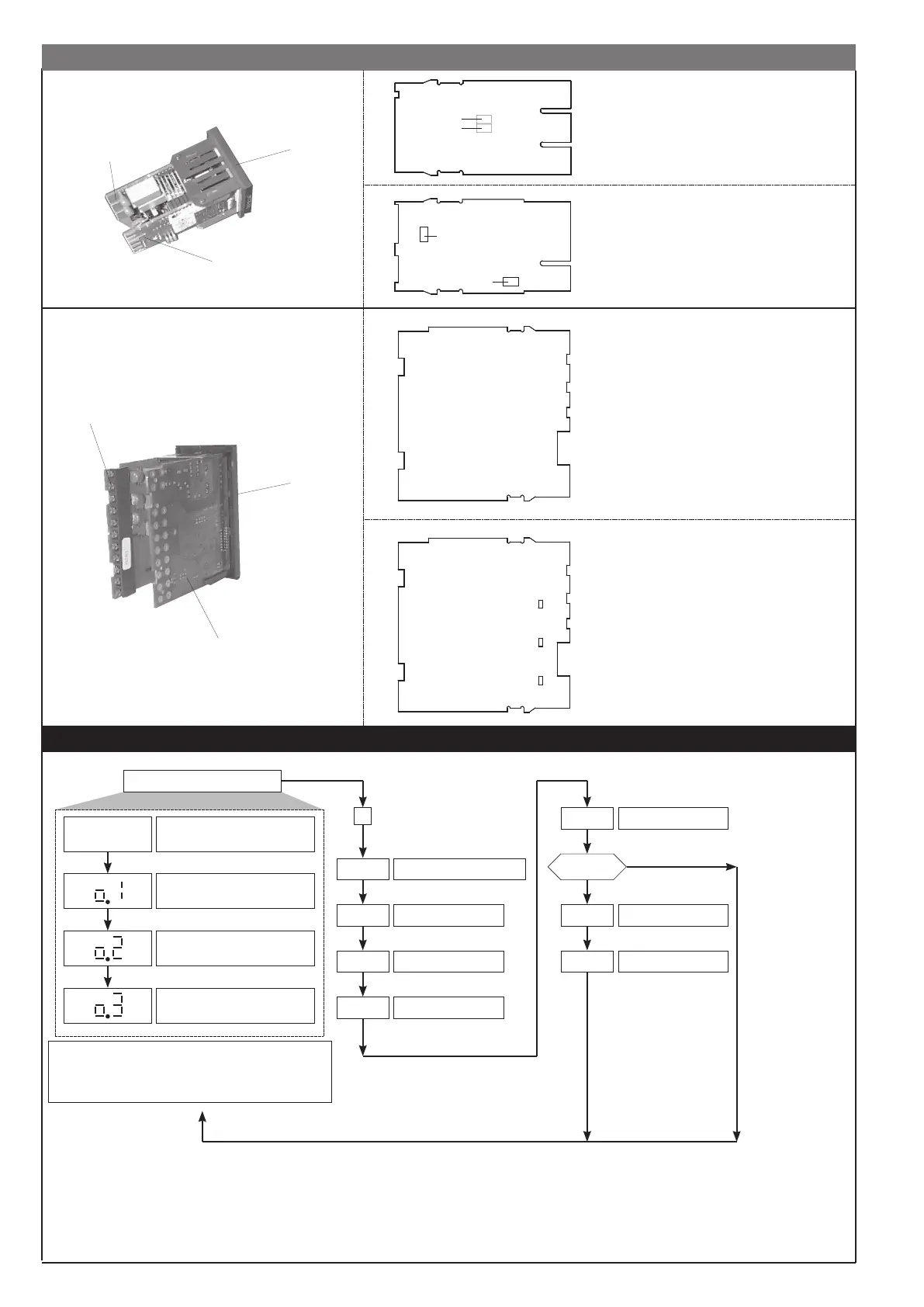
5 • PROGRAMMING and CONFIGURATION
(*) For deviation alarms the setpoint range is -999 ... 999
If the Inc, Dec, F keys are not pressed within 15 sec.,
the display returns to the P.V. value
I F
P.V.
Process variable
Alarm Setpoint Output 2 (*)
Alarm Setpoint Output 3 (*)
Password
C F
P A
PA = 99
P r
U.C.
User calibration
YES
NO
Alarm Setpoint Output 1
LEVEL 1 DISPLAY
Hysteresis parameters
Protection code
Information display
I n
Input settings
O u
Output settings
F
Pressed for
approx. 2 sec.
Keep the F key
pressed to browse
the menus.
Release the F
key to enter the
displayed menu.
Press the F key
to access the
parameters.
Keep the F key
pressed to exit any
menu at any time.
S1
A B
S5
S1 = Status of Out 3 relay
A = Direct
B = Inverse
S5 = ON with digital input
CPU BOARD
Device structure: identification of boards
S5 = Status of Out 1 relay
S6 = Status of Out 2 relay
A = Direct
B = Inverse
S6
S5
B A
POWER SUPPLY BOARD
CPU BOARD
POWER SUPPLY
BOARD
DISPLAY BOARD
S1
S3
S2
B
A
B
A
B
A
CPU BOARD + POWER
SUPPLY BOARD
OUTPUT BOARD
S1 = Status of Out 1 relay
S2 = Status of Out 2 relay
S3 = Status of Out 3 relay
A = Direct
B = Inverse
CPU BOARD + POWER
SUPPLY BOARD
OUTPUT BOARD
DISPLAY BOARD
3
81661G_MHW_40A48-96_09-2016_ENG
 Loading...