1 • INSTALLATION
• Dimensions and cut-out; panel mounting
Panel mounting:
Fix the device with the bracket provided before making any electrical
connections.
To mount two or more devices side by side, use the cut-out dimensions
shown above.
CE MARKING: The instrument conforms to the European Directives
2004/108/CE and 2006/95/CE with reference to the generic standards:
EN 61000-6-2 (immunity in industrial environment) EN 61000-6-3 (emission
in residential environment) EN 61010-1 (safety)
MAINTENANCE: Repairs must be done out only by trained and
specialized personnel. Cut power to the device before accessing
internal parts.
Do not clean the case with hydrocarbon-based solvents (Petrol,
Trichlorethylene, etc.). Use of these solvents can reduce the
mechanical reliability of the device. Use a cloth dampened in ethyl
alcohol or water to clean the external plastic case.
SERVICE: GEFRAN has a service department. The warranty excludes
defects caused by any use not conforming to these instructions.
2 • TECHNICAL SPECIFICATIONS
105
10
108
96
48
44,5
92
70
115
For correct and safe
installation, follow
the instructions and
observe the warnings
contained in this
manual.
!
FUNCTION CABLE LENGTH.
USED
TC input probe 0,8 mm
2
compensated 5 mt
“PT100” input 1 mm
2
3 mt
probe
Power supply cable 1 mm
2
1 mt
Relay output cables 1 mm
2
3,5 mt
EMC conformity has been tested with the following connections
Display
Keys
Accuracy
Thermal drift
Resolution
(unction of settable sample
time)
Main input
Thermocouples
Cold junction error
RTD type (scale configurable
within indicated range, with or
without decimal point)
Max. RTD line resistance
PTC type / NTC type
Max non-linearity error
°C / °F selection
Linear scale range
Logic input
Function of logic
input
Alarms
(Trip points)
Alarm
masking
Relat contact
Logic output
Triac output
Fault settings
Transmitter / Sensor power
Supply (option)
Analog retransmission
(option)
Power supply
(switching)
Fuse (inside device, not
operator serviceable)
Faceplate protection
Working / Storage temperat.
Relative humidity
Environmental conditions of use
Installation
Weight
3, 4 digit red LED’s digit height 20mm (3 digits),
digit height 14mm (4 digits)
3 mechanical keys (Raise, Lower, F)
0.2% f.s. at 25°C, amb. temperature ts
=120msec
0.005% f.s./°C
120msec, >14bit
60msec, >14bit
(only for linear inputs)
30msec, >13bit (only for linear inputs)
15msec, >12bit (only for linear inputs)
TC, RTD, PTC, NTC
60mV, 1V Ri ≥ 1MΩ; 5V, 10V Ri ≥ 10KΩ
20mA, Ri = 50Ω. adjustable digital filter
J, K, R, S, T, B, E, N (IEC 584-1, CEI
EN 60584-1, 60584-2) L GOST, U, G, D, C.
Custom linearization available on request
0,1° / °C
DIN 43760 (PT100), JPT100
20Ω
990Ω, 25°C / 1KΩ, 25°C
See tP parameter
Faceplate configurable
-1999...9999 (with 4 digit display)
-999...999 (with 3 digit display); punto
Configurable decimal point position, possible
3 segment linearization
24V, 5mA or no-voltage contact
configurable to reset memory latch, hold,
flash, zero, select max./ min. peak, peak-
peak value
Maximum of three configurable alarms:
absolute, deviation, symmetrical deviation.
Adjustable hysteresis
- exclude on power-up
- latch reset from key and/or external contact
- insert delay filter (DON, DBI, DOF, DPO)
- set minimum intervention time
NO (NC) 5A 250Vac, 30Vdc
24Vdc, 10V at 20mA, limitation to 30mA
20...240Vac ±10%, 3A max. Snubberless,
inductive and resistive load I
2
t = 128A
2
S
Alarm states can be configured in probe
fault condition
24V ±10%, 50mA
15V for transmitter, max. 50mA
1,2V for potentiometer > 100Ω
10V Rmin 50K - 0/4...20mA Rmax. 500Ω
resolution 12bit
(std) 100...240Vac/dc ±10%, 50/60Hz, 18VA
(opt) 11...27Vac/dc ±10%, 50/60Hz, 11VA
100 to 240VAC/DC -type T-500mA-250V
11 to 27VAC/DC - type T - 1,25A - 250V
IP65
0 to 50°C / -20 to 70°C
20 to 85% Ur non condensing
for internal use only, altitude up to 2000m
Panel mounting, extractable from front
320 g
for the complete version
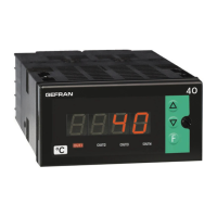
40T 96
UNIVERSAL TEMPERATURE and PRESSURE INDICATOR - ALARM UNIT
SOFTWARE VERSION 3.2x (includes R77 version)
code 81641I / edition 15 - 07-2011
INSTALLATION and
OPERATION MANUAL
1
81641I_MHW_40T96_07-2011_ENG