EasyManua.ls Logo

gefran 40T96 User Manual

gefran 40T96
10 pages
To Next Page IconTo Next Page
To Previous Page IconTo Previous Page
Page #2 background image
3 • DESCRIPTION OF FRONT PANEL
Use wires of
adequate thickness
(min. 1mm
2
)
PT100, JPT100,
PTC, NTC
• Pt100 / PTC / NTC
3
1
2
3-wire
PT100
2-wire PT100
PTC / NTC /
Generic user
configurable outputs
Out1
- relay 5A/250Vac
- Triac
20...240Vac ±10%
1A max
Out2
- relay 5A/250Vac
- logic 24V/20mA,
Out3
- relay 5A/250Vac
Available thermocouples:
J, K, R, S, T, B, E, N,
L, U, G, D, C
- Respect polarities
- For extensions,
use compensated
cable appropriate for
thermocouple.
dc current
linear input
20mA, Ri = 50Ω
dc voltage
linear input
60mV, 1V
Ri > 1MΩ
5V, 10V
Ri > 10kΩ
“Raise” and “Lower” keys:
These keys are used for any operation that
requires a numerical parameter to be raised or
lowered. •• The speed of change is proportional
to the time the key is pressed. •• The operation
is not cyclic: once the maximum (minimum) limit
is reached, there will be no further increase
(decrease) of the value, even if the key remains
pressed.
The keys can be configured to perform
reset, hold, display of the peak value, etc. as
determined by the ‘t.U.’ and ‘t.d.’ parameters on
the ‘In’ menu.
Function key:
Gives access to different configuration stages ••
Confirms any parameter changes
Standard:
100 to 240VAC/DC
±10%
Optional: 11 to
27VAC/DC ±10%
50/60Hz, 8VA max.
• Linear (V)
• Outputs
2
1
+
-
• Linear (I)
4
1
2
-
+
12
14
13
15
Out3
-
+
Out2
• Power supply
11
10
~
~
+
-
• Inputs
Thermocouples
2
1
4
2
3
1
+
-
+
+
S
-
Ri = 50Ω
to connect for 20mA input
4
2
3
1
+
-
+
+
-
Ri = 50Ω
4...20mA
Linear input with 3-wire transmitter
Linear input with 2-wire transmitter
PWR
Indication of output states:
OUT 1 (Alarm 1); OUT 2 (Alarm 2);
OUT 3 (Alarm 3); OUT 4 (Alarm 4)
114 5 1083 972 61
1219 18 131520 141621 1722
!
Label with engineering units
16
17
Out1
4 • CONNECTIONS
Digital input
24V, 5mA
or no-voltage
contact
6
5
+
-
• Digital input
Analog retrans.
output
0...20mA,
Rmax. 500Ω
0...10V
Rmin. 10KΩ
Out4
- relay 5A
250Vac
8
7
Retransmiss. output/Out4
+
-
R
• Linear input 1V for potentiometer
4
2
3
1
R >100Ω
External
supply
PV display: Indication of process variable
Indication of ‘HI’ or ‘Lo’ out of range Indication
of open circuit (br) or short circuit (Er)
•• Display of configuration and calibration
messages
T
T
~
~
Load
VT VT
Modbus 4 wires
/ Cencal
Modbus 2 wires
(Standard)
• Serial line
RS485 isolated serial line
For configuration Modbus 4 wires/Cencal
sees sheet technical
20
22
21
19
21
20
+
22
-
+
-
GND
B
(data -)
A
(data +)
Rx
Tx
24V or 15V 24V or 15V
Generic user
configurable
outputs
Out1
- relay
5A/250Vac
Out2
- relay
5A/250Vac
Standard:
100 to 240VAC/DC
±10%
Optional: 11 to
27VAC/DC ±10%
50/60Hz, 8VA max.
• Outputs
8
9
7
no
• Power supply
11
10
~
~
PWR
114 5 1083 972 61
1219 18 131520 141621 1722
!
6
5
Out2
~
~
Load
c
nc
Out1
Inputs
Mod. 40T 96 _ _ 2R (base)
Mod. 40T 96 _ _ RR/RD/T0 (expandible)
2
81641I_MHW_40T96_07-2011_ENG
-
+
+ 1,2V
Question and Answer IconNeed help?

Do you have a question about the gefran 40T96 and is the answer not in the manual?

gefran 40T96 Specifications

General IconGeneral
Brandgefran
Model40T96
CategoryMonitor
LanguageEnglish

Summary

1. INSTALLATION

Dimensions and Cut-out for Panel Mounting

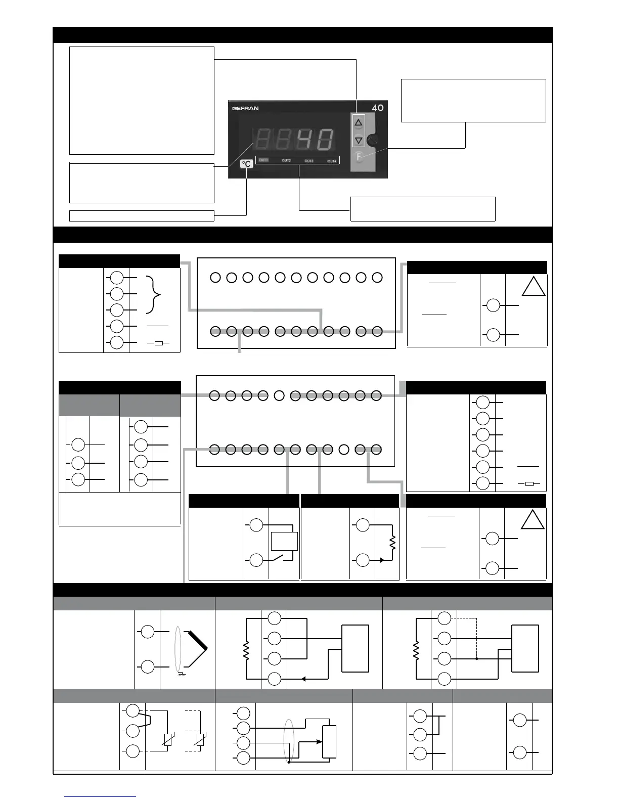
Details panel dimensions and cut-out requirements for device installation.

2. TECHNICAL SPECIFICATIONS

3. DESCRIPTION OF FRONT PANEL

4. CONNECTIONS

Output Terminal Connections

Describes various output configurations and terminal assignments for the device.

Serial Line and Communication Connections

Explains serial communication interface options and wiring for Modbus and Cencal.

Digital Input and Analog Retransmission Connections

Details digital input configuration and analog retransmission output options.

Input Signal Connections for Sensors

Covers connections for various input types like thermocouples, RTD, PTC, NTC, and linear signals.

Device Structure: Identification of Boards

Output Board and Jumper Identification

Identifies the output board and its jumper settings for configuration.

Display Board and Configuration Options

Describes the display board and its role in configuration and output status.

CPU and Power Supply Board Identification

Details the CPU board and power supply unit, including jumper settings.

5. PROGRAMMING AND CONFIGURATION

Level 1 Display and Menu Navigation

Explains navigating the device's menu structure and accessing parameters via the front panel.

Hysteresis Parameters Configuration

Hysteresis Settings for Alarm Trip Points

Defines hysteresis values for alarm trip points, allowing adjustment of alarm behavior.

Information Display and Status

Viewing Software, Instrument, and Hardware Versions

Shows how to view software version, instrument code, and hardware configuration details.

Serial Communication Settings

Virtual Instrument Input/Output and User Interface Setup

Configures serial communication settings, including virtual inputs, outputs, and user interface.

TC/LIN Input Parameter Settings

Input Signal Type, Scale, and Decimal Point Configuration

Sets up probe types, signal scaling, and decimal point positions for various inputs.

Digital Filter Configuration for Input Signals

Configures digital filters for main input signals and process variable display.

Input Offset Correction and Digital Input Function

Adjusts input offset correction and selects the function for digital inputs.

Input Scale Limits and Alarm Set Point Configuration

Defines minimum/maximum limits for input scales and alarm set points.

Output and Alarm Parameter Configuration

Alarm Type, Mode, and Hysteresis Settings

Configures alarm types, output modes (direct/inverse), and hysteresis for up to four alarms.

Output Filter Modes and Delay Settings

Sets up output filter modes (DON, DBI, DOF, DPO) and delay times for alarm outputs.

Custom Input Linearization

Linearization Step and Value Mapping

Defines custom linearization steps for input signals, mapping input values to output values.

User Calibration Procedures

Calibrating Analog Output and Custom Sensors

Guides through calibrating analog outputs, custom sensors (RTD, PTC, NTC), and potentiometers.

Protection and Access Control

Setting Parameter Protection Codes

Sets up protection codes to restrict access to specific parameters and pages.

Special Input and Output Functions

HOLD and FLASH Function Operation

Explains HOLD and FLASH functions, freezing input values and controlling output states.

6. ALARMS

Absolute Alarm Configuration and Behavior

Details normal and symmetrical absolute alarms with hysteresis, including inverse and direct modes.

Deviation Alarm Configuration and Behavior

Describes normal and symmetrical deviation alarms, specifying their behavior and configuration.

Output Filtering and Configuration Interface

Output Filtering Diagrams (F.0, r.A)

Illustrates filtering effects (DON, DBI, DOF, DPO) on output behavior relative to alarm setpoints.

PC Software and Kit for Instrument Configuration

Introduces the GF_express software kit for PC-based instrument configuration and data management.

Ordering Code Information

Instrument Ordering Code Structure and Options

Provides the structure and options for generating the instrument's ordering code.

Order Code Configuration Options

Transmitter Power, Communication, and Input/Output Options

Lists options for transmitter power supply, digital communication, and digital input/output configurations.

Safety Warnings and Precautions

Installation, Connection, and Electrical Safety Guidelines

Outlines critical safety warnings for installation, wiring, power supply, and handling to prevent hazards.

Related product manuals