Available thermocouples:
J, K, R, S, T, B, E, N,
L, U, G, D, C
- Respect polarities
- For extensions, use
compensated cable
appropriate for
thermocouple.
Use wires of adequate
thickness (min. 1mm
2
)
PT100, JPT100,
PTC, NTC
dc current
linear input
20mA, Ri = 50Ω
(signal must be isolated
from power supply)
dc voltage linear input
60mV, 1V, 5V, 10V,
Ri ≥ 500KΩ
(signal must be isolated
from power supply)
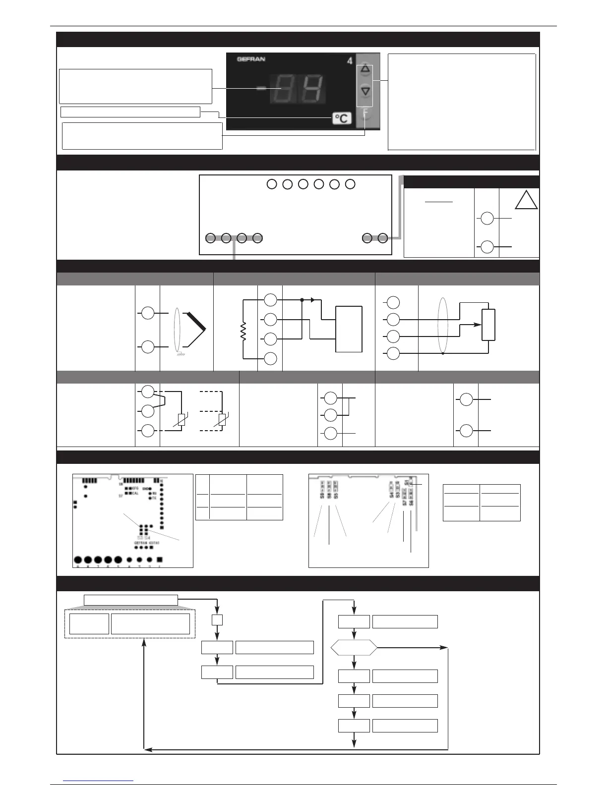
“Raise” and “Lower” keys:
These keys are used for any operation that requires
a numerical parameter to be raised or lowered. ••
The speed of change is proportional to the time the
key is pressed. •• The operation is not cyclic: once
the maximum (minimum) limit is reached, there will
be no further increase (decrease) of the value, even
if the key remains pressed.
The keys can be configured to perform reset, hold,
display of the peak value, etc. as determined by the
‘t.U.’ and ‘t.d.’ parameters on the ‘In’ menu.
3 • DESCRIPTION OF FRONT PANEL
Function key:
Gives access to different configuration stages •• Confirms
any parameter changes
Standard:
11...27Vdc ±10%
18...27Vac ±10%
50/60Hz, 3VA max.
not isolated
• Linear (V)
• Pt100 / PTC / NTC
3
1
2
2
1
+
-
• Linear (I)
4
1
2
-
+
• Power supply
11
12
~
~
+
-
• Thermocouples
2
1
4
2
3
1
-
+
-
Ri = 50Ω
4...20mA
• Linear input with 2-wire transmitter
PWR
12411321
!
Label with engineering unit
4 • CONNECTIONS
3-wire Pt100
2-wire PTC /
NTC / Pt100
+
PV display: Indication of process variable
Indication of ‘HI’ or ‘Lo’ out of range •• Indication of
open circuit (br) or short circuit (Er) •• Display of
configuration and calibration messages
5108976
T
T
• Linear input for potentiometer
4
2
3
1
R >100Ω
+ 1,2V
-
• Device structure: identification of boards
S3
S4
CPU board
PROBE POWER board
RTD, PTC, NTC
input
ON
OFF
Transmitter and
potentiometer
power supply
OFF
ON
S3
S4
S9
S8
S5
S1
S4
S6
S3
S7
Voltage
1V
24V (18V)
Jumpers
S4 - S6B - S7A
S6B - S7A
Probe power supply
• Inputs
5 • PROGRAMMING and CONFIGURATION
I F
P.V.
Process variable
Password
P A
PA = 99
P r
U.C.
Custom linearization
User calibration
YES
NO
LEVEL 1 DISPLAY
L n
Protection code
Information display
I n
Input settings
F
Pressed for
approx. 2 sec.
Keep the F key
pressed to browse
the menus.
Release the F key
to enter the
displayed menu.
Press the F key to
access the
parameters.
Keep the F key
pressed to exit any
menu at any time.
2
81606B_MHW_4T72_0609_ENG
 Loading...