7
www.geiger.de
EN
EN
8. Information for the specialist electrician
H
Caution: Important installation instructions.
Please follow all instructions since
incorrect installation can lead to
the destruction of the motor and the
switching unit.
• A locking switch is here necessary (no simultaneous
UP and DOWN commands).
• The operations with the service clamps may be
accomplished only by an electrical specialist.
• Motors with electronic limit stops can be connected in
parallel.
• In this case the maximum load of the switching unit
must not be exceeded.
• When changing the running direction the switchover
must be effected through an off-position.
• When changing the running direction the switchover
time must be at least 0.2 s.
• With a three-phase network, please use the same
external conductor in order to control the UP and
DOWN directions.
• Connecting cables with plug connectors of the
Hirschmann Company are tested and approved with
couplings of the Hirschmann Company.
• In order to prevent a malfunction caused by coupling,
the supply line (ref. NYM) from the actuator/switch to
the motor must not exceed 100m in case of motors with
electronic end stops.
H
Attention: the connection diagram of the
4 or 5 pole-connector is different. A 4-pole connecting cable must be
used for the motors. The GEIGER Flat4 with light blue ring. The motor
might start running unexpectedly if a 5-pole connecting cable with
continuous power supply is used.
9. Setting of the end stops
General information
In order to set the end positions of the GJ56.. E06 motors, any setting switch can be used that
has a programming key or that allows a simultaneous UP/DOWN command. In this case, the
UP/DOWN keys must be activated simultaneously instead of the programming key.
The motor can also be operated with the limit stop switch and a standard switch.
Article number / GEIGER setting switch
M56F152 with service terminal (D), 5 wires, SMI compatible
M56F153 with service terminal (CH), 5 wires, SMI compatible
M56F154 with service terminal (D), 4 wires
I
Important: please observe the connecting diagram on the back of the
setting switch.
Factory setting
• The motor is set on the lower end position at the factory. The upper end stop is at the very
other end. (at least lower end stop + 200 motor rotations).
• The motor command is in normal operation.
• The referencing is enabled on delivery.
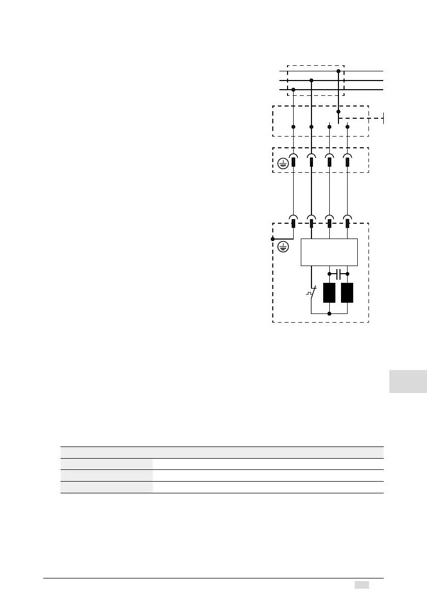
12 3
PE N
L1
N
Electronic /
mechanical
limit stop
blue
brown
black
green/yellow
 Loading...