<5>
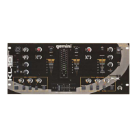
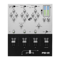
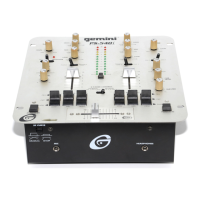
CS-02 PROFESSIONAL 5-CHANNEL STEREO FX MIXER
INTRODUCTION:
Congratulations on your purchase of a Gemini CS-02 Professional 5-
Channel Stereo FX Mixer. The CS-02 will exceed your expectations for a
DJ mixer, with premium sound quality and a wealth of useful features. With
proper care and maintenance, your mixer will provide years of reliable per-
formance.
FEATURES:
- 5 Channels with pre-fader LED VU meters and 3-band rotary EQ
- 3 Mic, 10 Line, and 3 Phono/Line Convertible Inputs
- Master, Booth, Zone, and Record RCA outputs w/ Zone device selection
control
- 25 Channel-Assignable DSP effects with bright blue backlit LCD display
and 5-bank memory recall
- 6-Device Input routing matrix on each channel
- 30mm linear DSP parameter control
- Rotary Dry/Wet control
- Auto & Tap BPM counter with optional EFX tempo synchronization
- Faceplate-mounted RCA Rec Output and Aux Input
- Dedicated faceplate-mounted ¼" XLR combo mic input with 3-band EQ
and Talkover Function
- Master, Booth, and Zone outputs with independent rotary volume con-
trols
- XLR Master Balanced Output with master attenuation switch
- Balance control with Mono switch
- Push button Cue Section with CUE/PGM control & Split Cue function
- Large blue backlit EFX On/Off button
- Replaceable faders with X-Fader Curve Control
- X-Fader assignment on each audio input channel
- Dual VU master meters
- 19" Rack ears included
CAUTIONS:
1. All operating instructions should be read before using this equipment.
2. To reduce the risk of electrical shock, do not open the unit. There are
NO USER REPLACEABLE PARTS INSIDE. Please refer servicing to a qual-
ified Gemini Sound Products service technician. In the USA: If you experi-
ence problems with this unit, please call 1 (732) 738-9003 for Gemini
Customer Service. Do not attempt to return this equipment to your dealer.
3. Do not expose this unit to direct sunlight or to a heat source such as a
radiator or stove. When operating, ensure that the unit has adequate ven-
tilation.
4. This unit should be cleaned only with a damp cloth. Avoid solvents or
other cleaning detergents.
5. When moving this equipment, it should be placed in its original carton
and packaging. This will reduce the risk of damage during transit.
6. DO NOT EXPOSE THIS UNIT TO RAIN OR MOISTURE.
7. DO NOT USE ANY SPRAY CLEANER OR LUBRICANT ON ANY CON-
TROLS OR SWITCHES.
CONNECTIONS / SETUP:
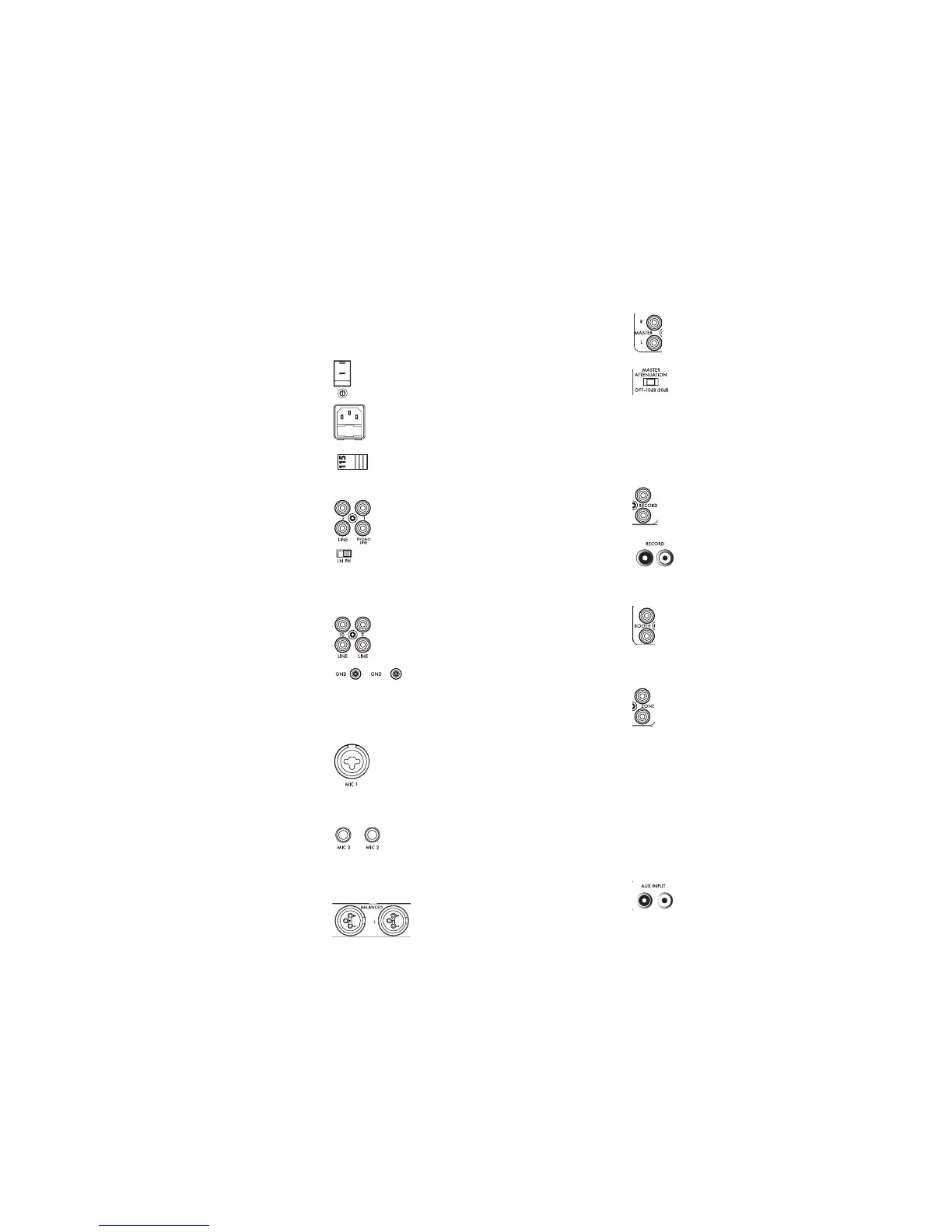
1. P
OWER SWITCH: The POWER SWITCH (67) turns the unit ON or OFF.
Make sure the switch is in the ‘OFF’ position prior to making any con-
nections.
2. AC I
NLET W
/FUSE: The AC I
NLET (65), located on the rear of the
unit, is the connector which accepts the AC P
OWER CABLE
(sup-
plied) used to power the unit.
3. V
OLTAGE SELECTION SWITCH: The VOLTAGE SELECTION SWITCH (66)
allows the unit to operate on either 115 or 230 volt configura-
tions, for worldwide operation. Prior to using the unit, make
sure that this switch reflects the voltage supplied in your locality.
4. P
HONO/LINE INPUTS (42, 45, 48) and PHONO/LINE SELECTION
SWITCHES (43, 46, 49): These inputs allow for the connection of
a phono-level turntable or a line-level device. If you are connect-
ing a phono-level device, you must switch the corresponding
P
HONO/LINE SELECTION SWITCH to the PH position. When using a line-
level device, such as a CD player, the corresponding PHONO/LINE
SELECTION SWITCH must be set to the LN position. Note that if the repsec-
tive PHONO/LINE SELECTION SWITCH is not in the correct position, it may
result in inaudible or distorted sound.
5. L
INE INPUTS (44, 47, 50, 51, 52, 53, 54): These inputs will acco-
modate an analog line-level signal, such as that from a CD play-
er.
6. G
ROUND TERMINAL: When using turntables with the
P
HONO/LINE I
NPUTS
(42, 45, 48), it will be necessary to
connect the GROUND TERMINAL (55), to eliminate hum. With the Power OFF,
Simply fasten the grounding fork (included with the turntable’s Phono
Cable) underneath any of the GROUND TERMINALS (55) found on the rear of
the mixer.
7. XLR-1/4” C
OMBO MIC 1 INPUT (1): This input is found on the
face of the mixer, and is used for connecting microphones that
are terminated with a 1/4” or XLR connector. This input is con-
trolled solely by the volume and EQ controls found directly
below the jack. For more information about using these controls, see the
Functions section.
8. M
IC 2 AND MIC 3 1/4” INPUTS (57, 58): These inputs are used
for connecting additional microphones that are terminated
with a 1/4” connector. This is useful for situations that require
multiple microphones to be used at the same time. Keep in mind, howev-
er, that the using the M
IC 2 AND MIC 3 1/4” INPUTS will require that they
occupy audio Channels 1 and 2 on the mixer.
9. B
ALANCED XLR MASTER OUTPUTS
(59): These audio
outputs carry balanced audio signals from the Master
bus of the mixer. Pin 2 is hot, Pin 3 is cold, and Pin 1
is ground. The MASTER VOLUME CONTROL (30) determines the level of audio
which is sent to these outputs.
10. RCA M
ASTER OUTPUTS (60): These audio outputs carry unbal-
anced audio signals from the Master bus of the mixer. The MASTER
VOLUME CONTROL (30) determines the level of audio which is sent
to these outputs.
11. M
ASTER VOLUME ATTENUATION SWITCH (61): This switch allows
you to decrease the dB output of the M
ASTER OUTPUTS (59, 60).
This is useful for situations where the output voltage of the mixer
needs to be adjusted for use with certain PA and recording setups. By
default, it is OK to leave the MASTER V
OLUME ATTENUATION SWITCH
in the
‘OFF’ position. If you notice that the output seems overdriven, or that the
maximum volume level that you wish to achieve is reached before the
M
ASTER LED VU M
ETER
(24) approaches 0dB, you may move the MASTER
VOLUME A
TTENUATION SWITCH
to the ‘-10dB’ or ‘-20dB’ position.
12. R
ECORD RCA OUTPUTS (28, 62): These outputs is best suited for
connecting a recording device, as it is not altered by the M
ASTER
VOLUME CONTROL (30), MONO BUTTON (32), or BALANCE CONTROL (29).
This is useful in a live setting when you are required to change the
overall volume of your output, but you do not want to change
the level (or properties) of audio being fed to the recording
device. The Face-mounted R
ECORD RCA OUTPUTS (28) are useful
for connecting a recording device when the rear of the mixer is not easily
accessible.
13. B
OOTH RCA OUTPUTS (63): This output is typically used to control
only the volume level sent to a monitoring system that is used with-
in the DJ booth. Although these RCA line-level outputs can be used
for virtually anything, they are designed to allow a performing DJ to
control the level of his monitors while spinning. Changing the level of the
booth outputs is accomplished by using the B
OOTH VOLUME CONTROL (31).
14. Z
ONE RCA OUTPUTS (64): This output differs from the rest of the
outputs on this mixer, in the sense that any one of the Audio
Channels (1 through 5), or the Master, can be assigned directly to this
output by using the Z
ONE SELECT CONTROL
(25). When one of the
Audio Channels (1 through 5) is assigned to the Zone Bus, it is sent Pre-
Fader to the Z
ONE RCA OUTPUTS
. An example of this would be a club that
has two rooms with separate systems but only one DJ. The DJ could have
a lounge music CD playing through Channel 1, with the CHANNEL VOLUME
F
ADER
(22) all the way down, and the Z
ONE SELECT CONTROL
(25) set to
Channel 1. The audio system in the second room, being driven by the
Zone Bus would output only the lounge music connected to Channel 1,
while the DJ could be actively spinning a completely different style of
music using the other channels on the mixer, which would only be output
to the system in the main room, connected via the M
ASTER OUTPUTS (59,
60).
15. A
UXILARY RCA INPUTS (27): These inputs can be used to con-
nect any line-level audio device when the rear panel is not easi-
ly accessible. The audio being fed to these jacks can be assigned to
Channels 4 or 5 by using the respective D
EVICE/CHANNEL ASSIGN KNOBS (8).
 Loading...