4 InstallationandOperatingInstructions
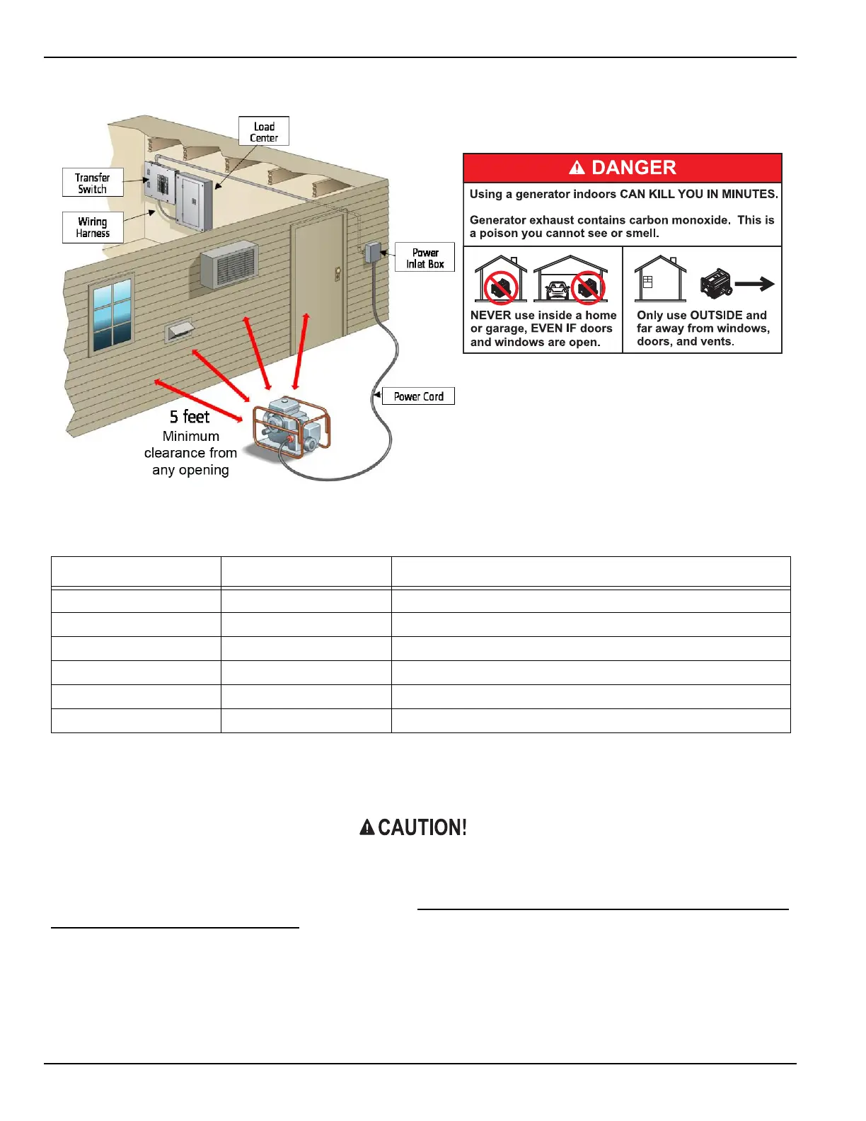
Figure 1: Planning Your Installation
Step 2 – INSTALLATION PROCEDURE
PLEASE READ THIS MANUAL IN ITS ENTIRETY BEFORE ATTEMPTING TO UNPACK, ASSEMBLE, INSTALL, OPERATE OR
MAINTAIN THIS EQUIPMENT. HAZARDOUS VOLTAGES ARE PRESENT INSIDE TRANSFER SWITCH ENCLOSURES THAT
CAN CAUSE DEATH OR SEVERE PERSONAL INJURY. FOLLOW PROPER INSTALLATION, OPERATION AND MAINTE-
NANCE PROCEDURES TO AVOID HAZARDOUS VOLTAGES. TURN OFF THE MAIN CIRCUIT BREAKER IN THE LOAD CEN-
TER BEFORE STARTING INSTALLATION.
I. TRANSFER SWITCH INSTALLATION:
1. Select a location on the left or right side of the load center to mount transfer switch, as it is provided with a 24”
flexible conduit wiring harness. Remove the front cover of the load center, save the screws. Locate and remove
a knockout (KO) on the lower side of the load center that matches the conduit fitting size on the wiring harness.
Table 2: CIRCUIT WORKSHEET
Circuit
Amperage Appliance(s) or Circuits
A4 15A
B4 15A
A5 20A
B5 20A
A6 20A
B6 20A
 Loading...


