6 Owner’s Manual for Portable Generator
Connection Plugs
120 VAC, Duplex Receptacle
The 120 Volt outlet is overload protected by
the 15 Amp push button circuit protector. See
Figure 2-3. Each receptacle will power 120
Volt AC, single phase, 60 Hz electrical loads
requiring up to 1700 watts (1.7 kW).
Figure 2-3. 120 VAC, Duplex Receptacle
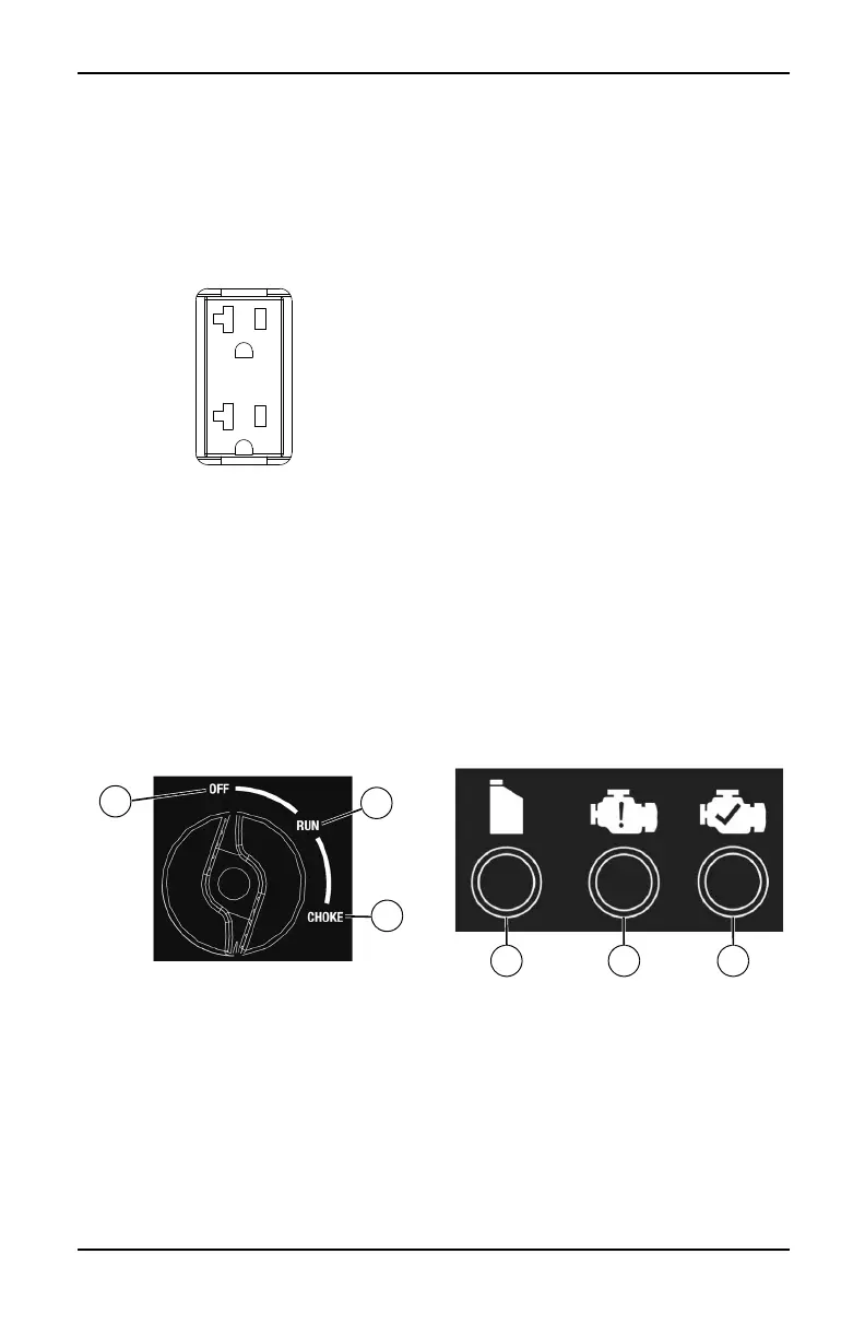
Off/Run/Choke Switch
This controls the ON/OFF functions, choke
and fuel valve operation. See Figure 2-4.
• The OFF position (1) stops the engine and
shuts off fuel flow.
• The RUN position (2) is for normal opera-
tion and to gradually reduce the use of the
choke.
• The CHOKE position (3) switches the fuel
valve on to start the engine.
NOTE: The CHOKE is not required to start a
warm engine.
Figure 2-4. Dial (example)
USB Outlet
The 5 VDC, 1.5 Amp USB outlet allows
charging of compatible electronic devices.
Economy Switch
The economy switch has 2 modes of opera-
tion:
• On: The quietest mode and best when run-
ning appliances or equipment that are
resistive loads (non-motor starting), (exam-
ple: TV, video game, light, radio).
• Off: Best when running a both inductive
(motor-starting loads) and resistive (non-
motor starting loads), especially when
these loads are turning on and off (exam-
ple: RV, air conditioner, hairdryer).
Generator Status Lights
See Figure 2-5.
• Overload LED (orange): Indicates system
overload (2). During motor starting it is nor-
mal for the overload LED to illuminate for a
few seconds. If LED stays illuminated and
the ready LED turns off, the engine will con-
tinue to run without output power. Remove
all applied loads and determine if attached
devices exceed recommended output
power. Check for faulty or shorted connec-
tions. To restore electrical output, turn dial
OFF to reset. Start engine. If condition was
corrected, the orange LED will not illumi-
nate and electrical output will be restored.
Loads can be applied once the green LED
illuminates. If the orange LED returns, con-
tact an IASD.
• Low Oil Level LED (red): Illuminates when
oil level is below safe operating level.
Engine shuts down (1).
• Power LED (green): Indicates output from
generator (3) (unless there is a low oil or
overload condition).
Figure 2-5. Status Indicators
Circuit Protectors
The AC receptacles are protected by an AC
circuit protector. The DC receptacles are pro-
tected by a DC circuit protector. If the genera-
tor is overloaded or an external short circuit
occurs, the circuit protector will trip. If this
occurs, disconnect all electrical loads to deter-
mine the cause of the problem before using
the generator again. Reduce the load if the cir-
cuit protector is tripped.
002347
 Loading...