General Information
Owner’s Manual for Australian 3-Phase 50 Hz Air-Cooled Generator Sets 7
Section 2: General Information
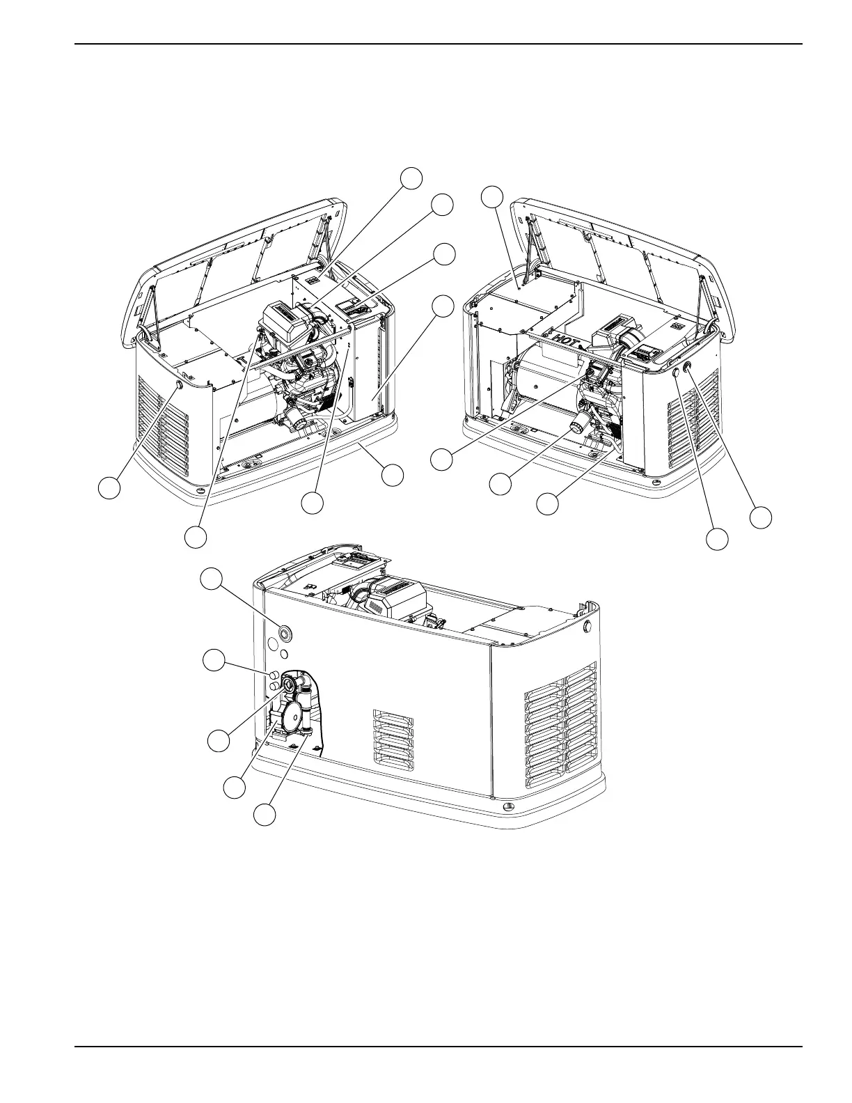
Generator Set Components and Controls
Figure 2-1. 20 kVA—Components and Control Locations
A Lock with cover F Exhaust enclosure L Composite base P Fuel inlet
B
Main line circuit breaker
(generator set disconnect)
G Status LED indicators M Data plate location Q Fuel regulator vents (2)
C Airbox with air cleaner H Oil drain N Sediment trap R Wi-Fi module
D Control panel J Oil fill cap O Fuel regulator S Oil dipstick
E
Battery compartment
(battery not supplied)
K Oil filter
 Loading...