Operation
14 Owner’s Manual for Australian 3-Phase 50 Hz Air-Cooled Generator Sets
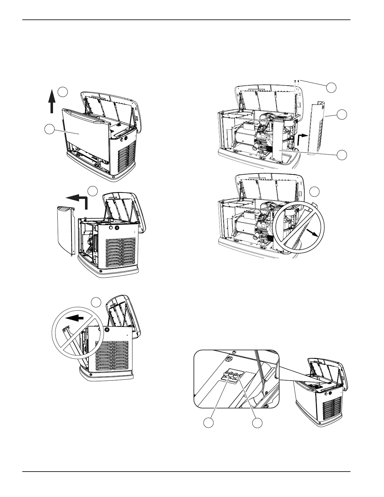
Front Access Panel Removal
See Figure 3-2. Remove front access panel (A) by lifting
it straight up and out once lid is open.
NOTE: Always lift front access panel straight up before
pulling away from enclosure (B, C). Do not pull panel
away from enclosure before lifting up (D).
Figure 3-2. Remove Front Access Panel
Intake Side Panel Removal
See Figure 3-3. Intake side panel (A) must be removed
to access the battery compartment, fuel regulator, and
sediment trap.
1. Raise lid and remove front panel.
2. Use a hex wrench to remove two mounting screws
(B) and L-bracket screw (C).
3. Lift intake side panel up and away from generator
set.
NOTE: Always lift intake side panel straight up before
pulling away from enclosure. Do not pull intake side
panel away from enclosure before lifting up (D).
Figure 3-3. Intake Side Panel Removal
Generator Set Main Line Circuit
Breaker (Generator Set Disconnect)
See Figure 3-4. This is a 3-pole main line circuit breaker
(MLCB) (generator set disconnect) (A) rated according to
relevant specifications.
Indicator (B) Identifier—Green means OFF (OPEN). Red
means ON (CLOSED).
Figure 3-4. Generator Set Main Line Circuit Breaker
(MLCB)
 Loading...