5
3.2.1 CLOSE TO UTILITY SOURCE SIDE
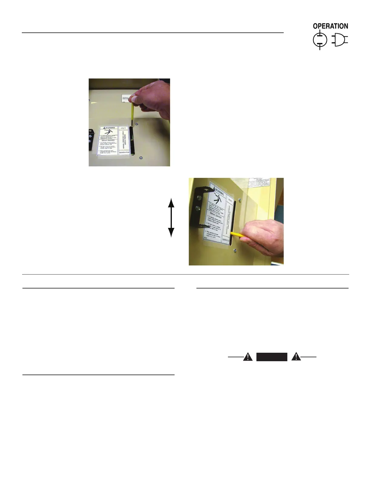
Before proceeding, verify the position of the switch by observing
the position of manual operation handle in Figure 3.1. If the handle
is UP, the contacts are closed in the NORMAL (UTILITY) position,
no further action is required. If the handle is DOWN, proceed with
Step 1.
Step 1: With the handle inserted into the moveable contact carrier
arm, move handle UP. Be sure to hold on to the handle as
it will move quickly after the center of travel.
Step 2: Remove manual operating handle from moveable contact
carrier arm. Return handle to storage bracket.
3.2.2 CLOSE TO GENERATOR SOURCE SIDE
Before proceeding, verify the position of the switch by observ-
ing the position of the manual operation handle in Figure 3.1. If
the handle is DOWN, the contacts are closed in the GENERATOR
(STANDBY) position. No further action is required. If the handle is
UP, proceed with Step 1.
Step 1: With the handle inserted into the moveable contact carrier
arm, move the handle DOWN. Be sure to hold on to the
handle as it will move quickly after the center of travel.
Step 2: Remove manual operating handle from moveable contact
carrier arm. Return handle to storage bracket.
3.2.3 RETURN TO UTILITY SOURCE SIDE
Step 1: Manually actuate switch to return manual operating handle
to the UP position.
Step 2: Remove manual operating handle from moveable contact
carrier arm. Return handle to storage bracket.
3.3 VOLTAGE CHECKS
1. Turn ON the UTILITY power supply to the transfer switch using
the UTILITY SERVICE DISCONNECT circuit breaker.
DANGER
PROCEED WITH CAUTION. THE TRANSFER
SWITCH IS NOW ELECTRICALLY HOT.
CONTACT WITH LIVE TERMINALS RESULTS IN
EXTREMELY HAZARDOUS AND POSSIBLY FATAL
ELECTRICAL SHOCK.
2. With an accurate AC voltmeter, check for correct voltage.
Measure across ATS terminal lugs N1 and N2. Also check N1
to NEUTRAL and N2 to NEUTRAL.
3. When certain that UTILITY supply voltage is correct and compat-
ible with transfer switch ratings, turn OFF the UTILITY supply to
the transfer switch.
4. On the generator panel, set the AUTO/OFF/ MANUAL switch to
MANUAL position. The generator should crank and start.
Section 3 — Operation
RTS “HS” Type Transfer Switch
Attach handle to
the moveable contact
carrier arm.
Move handle UP for the
NORMAL (UTILITY) position.
Move handle DOWN for the
GENERATOR (STANDBY)
position.
NOTE: Return handle to
storage position in enclosure
when finished with manual transfer.
Figure 3.1 — Actuating Transfer Switch

 Loading...


